Arithmetic and Logic
In this Chapter we’ll deal essentially with the Division, an operation solved by an iterative process. Specifically we will see how the computer executes a division of 8 bit numbers in two’s complement.
Before we proceed
We want to emphasize that, besides the analysis of a binary division, with a very relative impact in the overall context for the knowledge of a computer logical operation, this chapter has a huge contribution to the development of logical reasoning based on an effective knowledge of each component contribution and mainly in the deep analysis of how the signals are transmitted and propagate in time, the Clocked Logic.
The detail we’ll use analyzing each circuit line behavior, analyzing frames with the input and output values of the Edge Triggered Latches (ETL) and of the various circuit components in each clock cycle, isn’t obviously just to understand a circuit. Much more than that the purpose is to consolidate a logical reasoning, the knowledge of the various used components behavior and the signals propagation over time, both within each circuit component and in the circuit as a whole. This is the Clocked Logic at its best.
We consider this chapter as a touchstone in the knowledge of some of the circuits described in the previous chapter, through their practical application which will certainly consolidate our knowledge about them.
It will also give a good contribution to a better consolidation of Clocked Logic knowledge. We will always insist in the understanding of the signals values propagation within a circuit and in the input and output values at the ETL for each clock cycle.
We hope that after reading this chapter, the clock cycle and signals propagation will become part of our reasoning always we think about computing. We tried hard for that to happen.
Now, the binary Division .
We begin by developing the division algorithm, because that is the way to decompose any action we intend to teach the computer. In this chapter we will develop the algorithm of the division of two 8 bit binary numbers, where we run step by step what we do when we execute the operation by hand :
“Drop the first digit of the dividend and to see if the divisor fits in it, in other words if the subtraction between it and the divisor produces a positive result, or yet, if that digit is greater than the quotient. If it fits then post at the quotient the number of times it fits, which in our case is at most once (1). If it doesn’t fit then post 0 in the quotient. Drop the dividend second digit and proceed as above, and so on until the last digit of the divisor”.
This is what we’ll try to show graphically in this Chapter.
Then we associate the steps of this algorithm to the action of some logic circuits that we saw in the previous chapter, which will reproduce exactly the same we do in the algorithm, digit by digit, one per clock cycle.
Following the procedure that we have adopted until now, they shall be created through logical deductions resulting from the algorithm. The circuits will arise as performers of each of the algorithm steps and we’ll try to logically get to that conclusion.
The comparison will be the final paragraph of this arithmetic operation . Compare is a fundamental part of programming. A comparison always returns a boolean value, true or false, for real values comparison. Is 2 greater than 3? False (0)! Is 3+4 greater than 2-1? True(1)!
It is based on these boolean values that the Multiplexer will choose its input, or that the Demultiplexer will choose its output. For instance if a program follows its normal execution or performs a jump. Or, from where will come the value for an operation.
See the global synopsis of this work
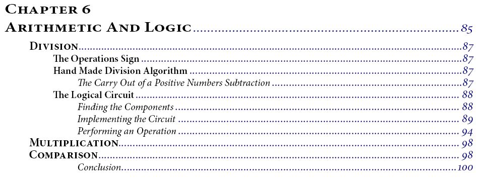
We introduce here the table of contents of the Paper Book to describe the themes approached in this Chapter

