
Binary Addition
Arithmetic operations? So far we only talked about logical gates with true or false responses. How is that going to make addition, subtraction, multiplication and division? How is it possible to achieve this, using combinations of logical gates in logical circuits, which reflect expressions of propositional logic that only return true or false?
Indeed, with only true or false as inputs and outputs in a circuit, it’s not easy to understand how we can do additions of numbers just as we know and work with them in our decimal numeral system. At least while we’ll think in decimal. But if we think and work in the binary numeral system, it may no longer be so difficult to understand. Just think that true and false are reflected in 1 and 0. As there are no other digits on this numerical base, any operations involving binary numbers can only return 1 or 0 digits. And that is precisely what the logical gates do. So, once again the logical reasoning will lead us to the appropriate combinations of logical gates in order we get our goal.
Let’s start with the addition, the source of all other operations. First, we have to learn how to add, i.e. we’ll have to do step by step something that we do almost intuitively since the first years of school, in order to define the addition algorithm. And now we will have to do it with binary numbers. And we’ll have to start by doing it just as we did with the decimal numbers in school. So, let’s take the paper and the pencil and let’s do it, considering exactly the same steps that we learned for the decimal system.
We will start by reviewing the steps we used to make an addition, when we did it in a piece of paper without any calculator, and from there we’ll establish the algorithm of that addition.
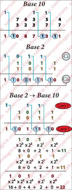
We’ll do it using two concrete numbers, for instance 76,564 and 32,377 using Figure 1 to help us developing the algorithm for the addition of two numbers.
- The two numbers are placed above each other digit to digit, both leaning to the right. Draw a line under the second (bottom) number.
- The digits are added column by column starting from the right to the left.
- The digits in the column are added and the result is written below them, under the drawn line, in that same column.
- If the result is bigger than 9 its because it has 2 digits. The digit on the right is written in that same column under the line. The digit on the left is written in the column on the left and above the digits being added. We call it the “carry digit”.
- If there are no more columns jump to step 7.
- If there are more columns jump to step 3.
- If the carry digit has value it’s written in the column at the left of the result.
- The addition is finished and the result is under the drawn line.
This is the algorithm of the addition of two numbers in the base 10. The algorithm in the base 2 is exactly the same. Only with the difference that in base 2 we have only two digits
0 + 0 = 0, 1 + 0 = 1, 0 + 1 = 1 e 1 + 1 = 2
Stop there! But 2 doesn’t exist in base 2, as 10 doesn’t exist in base 10 as a digit. The base represents the number of digits used to represent numbers in that base. Ten (0 to 9) in base 10, two (0 to 1) in base 2 and 16 (0 to F) in base 16.
Ten (10) is the name we give in decimal to the first number after the base digits are elapsed, the same number that in base 2 must be called one-zero (10).
Every time the number of digits of the base is elapsed we put a 1 at the left and begin again numbering from 0 at it’s right. And this is good for any base.
- In decimal after the 9 comes 10, after the 99 comes 100, after the 999 comes 1000, and so on.
- In binary after the 1 comes 10, after the 11 comes 100, after the 111 comes 1000 and so on.
- In hexadecimal after the F comes 10, after the FF comes 100, after the FFF comes 1000 and so on.
Thus, from now on we will no longer pronounce 10 as ten but as one-zero, 100 as hundred but as one-zero-zero, and so on. This way we will be using the same designation for all the positional numeral system bases. Thus, when we add 1 with 1 in base 2 we’ll have as result 10 (one-zero). We put the 0 in the same column below the line and put the carry 1 at the top of the first column at left.
Let’s try it adding 1011 with 1011, following step by step the algorithm that we have built, using the graphical representation in Figure 1.
But the computer doesn’t know this adding method. It was not with us in school when child and even if it did, our old master could not teach it the rules and mnemonics we use to add. It is stubborn and dumb and insists in only learning 1 and 0. It says its enough for it. And it’s true what it says, but it makes us think a lot to teach him how to solve our problems.
Once found the algorithm of the problem in the real world we are ready to elaborate a good logical reasoning seasoned with a little imagination, that enables us to find the logic gates whose properties, once combined with each other, will give the answer to our question.
Partial Adder
We are adding in base 2. The operands can only be numbers composed by the digits 1 or 0, just the same way the logical gates inputs are. And the result is always expressed in 1 and 0, as the logical gates outputs. Maybe what we’ve just stated turns more visible the way to find the solution with logical gates combinations.
We remember that
0 + 0 = 0, 1 + 0 = 1, 0 + 1 = 1 e 1 + 1 = 0 and carries 1
Reviewing this makes us remember the property of a logical gate which returns true only when the inputs are different, the eXclusiv OR or XOR.
We can notice that in the three first operations (0+0=0, 0+1=1, 1+0=1) XOR returns exactly the value of the result for those operands as its inputs.
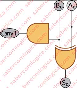
In the last operation (1+1=0 and carries 1) it will also return the value of the result for the column of the operands, being these its inputs. But it remains the question of the “carries 1”. And the XOR gate doesn’t guess if it carries 1 or not. It only knows that if its inputs (the operands) are equal it returns 0 and if they are different it returns 1. We must follow this description with Figure 2.
Carry 1 only exists when A0 and B0 are both 1. In all the other situations there will be nothing to carry. Well, so being why don’t we analyze both A0 and B0 with an AND gate in parallel with a XOR gate? AND will return 1 when both A0 and B0 will be 1, which can be the value of carry 1, and XOR in that case returns 0, the value to place at the bottom of that column. That’s it. We’ve got the solution.
Thus, we have found the way to add 2 bits with logical gates. This is the partial adder circuit, or the adder for the order 0 bit or first digit of the number to be added, the one at the most right. The sum of these bits will be given by S0 (the value that stays at the bottom of the column) and C0 (the value which is carried).
Why partial?
We have been referring until now the carry 1 which is an important element of an addition’s algorithm.
It’s the value resulting from the addition of the digits of one column which is transported to be added together with the digits of the column immediately at left.
As we said, it is carried out from the addition of this bits. Thus it must be carried in the addition of the bits of next order, i.e., it must be considered for the result of their addition.
Before going further on, let’s make a little consideration about this question of the carries, before we are all confused.
Carry In and Carry Out
The reference that we have been using until now of carry 1, results from an algorithm made by us humans for a real situation. If it carries something, we say carry something, but if it carries nothing, we simply say nothing. But this is in our world, not in the computer’s world.
For the computer, if there is the possibility of some value being carried in or carried out, that has to be considered in the circuit. The only thing that can change is the carried value, which will be 0 when nothing is carried.
In binary addition the carried values can only be 1 or 0, but the possibility to carry them has to be there. So, from now on we will adopt the designations of:
- Carry Out (Co) for the value that is transported out of the addition of 2 bits of any order to the addition of the 2 bits of higher order.
- Carry In (Ci) for the values that come transported from the lower order bits addition to be added together with this order bits.
The complete adder
The adder circuit for the bits of an order above 0 will be different from the one we have just seen, because the possibility of some value being carried into it will have to be considered.
We will call this one the complete adder circuit.
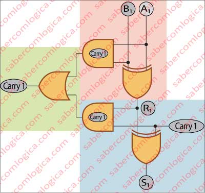
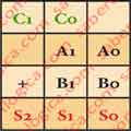
We must follow this description with Figure 3, where the first partial adder is shadowed in rose, the second partial adder is shadowed in blue and the combination of both Co is shadowed in green. In this Figure we include the physical representation in order you can follow the transistors behavior as the inputs change.
So, in this circuit we’ll have three bits to be added: the two bits of the column and the carry in (Ci) bit, or the carry out (Co) bit of the lower order bit addition.
But the solution we have found can only add two bits each time. How can we include the third bit in this?
By using two partial adder circuits in a serial connection. Thus, the result off the addition of the column bits, A1 and B1, i.e. the value returned by the XOR gate where they are the inputs, will be added with the Ci bit, i.e. both R1 and Ci will be the inputs of another XOR gate, being its output S1, the result of the column.
But two partial adders have two Co. How is that?
Actually it is like that. But the circuit can only have one Co, as the next circuit will only have a Ci too. So, we have to find a way of combining the two Co in only one. If the Co of the two bits A1 and B1 is 1, it’s because both they are 1. In this case, both 1, R1 will be 0. Thus, the Co resulting from the analysis of R1 and Ci can never be 1, because R1 is 0 and the AND gate only returns 1 when both inputs are 1.
Conclusion: Only one of the Co can be 1 for each addition. The two Co can be both 0, or 1 and 0, but never 1 and 1.
As the complete adder’s Co will result of the sum of both partial adder’s Co, the final Co will be 1 if anyone of the partial Co is 1 or 0 if both the partial are 0. This is exactly what an OR gate returns when its inputs are the partial Co. The situation when both inputs are 1 doesn’t fit in this gate’s return but that doesn’t matter because it will never happen. That’s it. We have found the solution for the complete adder or for the addition of bits of an order above 0. And also how the Computer can Sum.
We have frequently referred to the order of the bits, reason why we think its the moment to make clear what is the order of a bit.
The Order of the Bits
The bits are the digits of a binary number, being this one the Byte or the Word. In a positional numeral system the digits have their value according to their position in the number. It’s this position that we call the order.
In a number, the digits position begins at 0 for the first digit or the most right one and grows from there on as we walk until the last one or the far most at left.
In a Byte the bits begin by the order 0 bit, or less representative one, and go from there on growing until the order 7 bit, or most representative one. You must have noticed that we didn’t compare the order of the bits to its most right or most left positions and it wasn’t by accident. Normally, when a Byte is represented it is like a number, with its bits order growing from right to left. But not mandatorily like that. And for that reason, the bits in a Byte are represented by a letter with a number (its order) following it, such as X7 X6 X5 X4 X3 X2 X1 X0 which represents a Byte and its bits, but X0 X1 X2 X3 X4 X5 X6 X7 represents exactly the same byte.
We are referring this because during this work we will frequently see the Bytes represented in several positions: Left to right, right to left, top to bottom and bottom to top, according to the position of the component where the Byte and its bits are represented. For that reason the order of the bit in the Byte is always indicated by the number after the letter. And this is what prevails, not its position.
We referred the Byte but the same applies to the Word.
4 Bits Adder
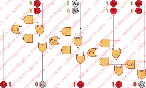
Until now we have only analyzed the sum of numbers with 1 bit. The order 0 for the partial adder and the order 1 for the complete adder. It’s time to put it all together adding two numbers of 4 bits, what we do in Figure 4 with the same numbers that we used in Figure 1, to show how we can add manually two binary numbers.
Notice that in this circuit we do no longer refer Ci and Co, but only C with a number after it, referring to the order bit from where it results. Actually, for this circuit the Carry In and the Carry out are the same, depending its name from the side we are looking to it. So we refer it only by C (Carry).
Try to replace the operands by other values and through the logical gates behavior analysis find the final result. Then compare it with the result of the sum of the same numbers in decimal, to see if you’ve done well.
What we have done so far in this Chapter was through logical reasoning, using what we know about logical gates to combine them in order to obtain a result. As we promised we would always do. Now we’ll find the algebraic expression for the Sum of two numbers of 2 bits. Two bits in order to get a partial and a complete circuits. For each output there is an algebraic expression, which is put together with other expressions in order to get the final result.
S0 = A0 XOR B0 or A0⊕B0 or NOT (NOT (A OR B) OR (A AND B)) or ¬(¬(A+B)+(A.B))
C0 = A0 AND B0 or A0∙B0
S1 = (A1 XOR B1) XOR C0 or (A1⊕B1)⊕C0 or NOT (NOT (NOT (NOT (A1 OR B1) OR (A1 AND B1)) OR (A0 AND B0)) OR (NOT (NOT (A1 OR B1) OR (A1 AND B1)) AND (A0 AND B0))) or ¬(¬(¬(¬(A1+B)1+(A1∙B1))+(A0∙B0))+(¬(¬(A1+B1)+(A1∙B1))∙(A0∙B0)))
C1 = (A1 AND B1) OR ((A1 XOR B1) AND C0) or (A1∙B1)+((A1⊕B1)∙C0) or (A1∙B1)+((NOT (NOT (A1 OR B1) OR (A1 AND B1)))∙(A0∙B0)) or (A1∙B1)+((¬(¬(A1+B)1+(A1∙B1))∙(A0∙B0))
S2 = C1
the final result being represented by the binary number S2 S1 S0 which in decimal will be S0 x 2º + S1 x 2¹+ S2 x 2².
In Figure 5 the operation is described as it would be executed by hand.
Comment
You certainly have noticed that we are introducing the algebraic expressions for all the circuits we have been analyzing until now, after their logical description. Those expressions are getting more complex as the circuits themselves do. Just look at this last one and try it replacing S2 S1 S0 by their Boolean expressions. The result will be huge and weird. And we are just doing a 2 bit number addition.
These expressions should be worked by the Boolean algebra rules and theorems and by empirical methods, like the Karnaugh maps for instance, in order to be simplified, something that is not in the scope of this work. The idea was to use them like an introduction to what we intend to write about logical mathematics. We will no longer write this expressions for circuits.