
Binary Counter
The task of a Binary Counter is to count pulses. For each clock cycle, the binary counter increases or decreases the number stored in its outputs, whether it is an Ascending or a Descending Counter.
A Binary Counter consists of a set of ETL which memorize an equal set of bits. In the analyzed solution the Clock acts simultaneously over all ETLs, these being connected in such a manner that each one’s input contains the information to be memorized as a function of the other’s behavior.
Ascending binary Counter
In order to build an Ascending Counter, it will be necessary to analyze how the digits of a binary number evolve as it becomes bigger. We will do it bit by bit, and we’ll try to find a standard behavior which will allow us to establish the algorithm and, consequently, find the logical solution.
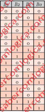
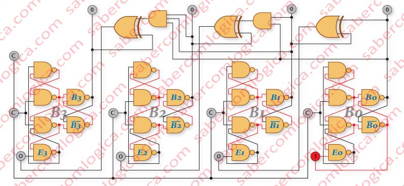
Let’s start by analyzing the table in Figure 1, representing the four 16-bit numbers, from 0000 (0) to 1111 (15), together with Figure 2, representing the logical circuit of a 4-bit Ascending Counter.
B3,B2,B1,B0 represent the bits in the table, as well as the outputs of a ETL Counter. E1,E2,E3,E4 represent the inputs. Once again, ETL means Edge Triggered Latch.
Regarding B0 we can verify that it changes its state at each transition, from 1→0 and 0→1. Thus, for each B0, we’ll have its denial at E0, so that, at the next Clock, its value can be memorized. In order to do this, we must connect ¬B0 to E0 at the ETL of order 0.
E0 = NOT B0
Regarding B1 we can verify that:
- B1 is 0 every time B1 and B0 are equal in the preceding number.
- B1 is 1 every time B1 and B0 are different in the preceding number.
If we apply a XOR operator to B0 and B1, it will return the value of E1 in each situation. Both different is 1, both equal is 0. At the following Clock, the desired value is memorized in B1.
E1 = B0 XOR B1
Regarding B2 we can verify that:
- B2 is 0 every time in the preceding number:
- B0 and B1 are not both 1 and B2 is 0 or
- B0 and B1 are both 1 and B2 is 1;
- B2 is 1 every time in the preceding number:
- B0 and B1 are both 1 and B2 is 0 or
- B0 and B1 are not both 1 and B2 is 1.
this repeated condition of B0 and B1 being, or not being, both 1, matches the application of an AND operator to B0 and B1, which only returns 1 if both are 1. So, in other words we can say that:
- E2 is 0 every time B0 AND B1 and B2 are equal.
- E2 is 1 every time B0 AND B1 and B2 are different.
This is the behavior of a XOR gate. If both are equal, it returns 0, if both are different, it returns 1.
So, if we connect B0 AND B1 and B2 to a XOR gate, its output will have the value of the next B2. Let’s connect it to E2, and at the next Clock, the desired value will be memorized in B2.
E2 = (B0 AND B1) XOR B2
Regarding B3 we will follow the same logical reasoning we did for B2, with the difference that now, at the AND gate input, we must have B0, B1 and B2.
- E3 is 0 when B0 AND B1 AND B2 and B3 are equal.
- E3 is 1 when B0 AND B1 AND B2 and B3 are different.
The same way, if we connect B0 AND B1 AND B2 and B3 to a XOR gate, its output will have the value of the next B3. Let’s connect it to E3, and at the next Clock, the desired value will be memorized in B3.
E3 = (B0 AND B1 AND B2) XOR B3
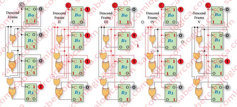
In Figure 3 we have a simplified representation of an ascending counter, where we can verify its implementation and its operation during 4 iterations.
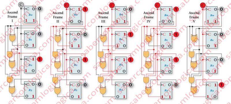
Frame I represents the starting point with a stabilized situation, and the Clock at the low state. At the outputs of the Counter is the initial value of 0100(4). At the inputs of the Counter are the values resulting from the connections between outputs and inputs, i.e. the value 0101(5), awaiting the next Clock in order to be memorized, which will happen in Frame II, the first of the 4 represented iterations. Frames III, IV and V represent the remaining 3 iterations which will take the counter to its final value 1000(8). Each iteration is a single Clock.
During each iteration, the values at the inputs are memorized, and the inputs assume values resulting from their connections to the memorized ones, waiting for the next Clock to repeat the operation.
As initially defined, we can now conclude that the Counter’s ETLs contain, at each moment, at their inputs, the information to be memorized resulting from its previous behavior, and that they are simultaneously actuated by the Clock.
Descending binary Counter
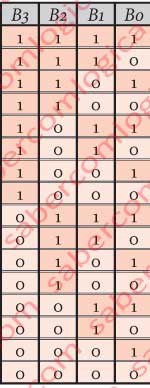
Let’s start by analyzing the table in Figure 4, representing the 16 4-bit numbers from 0000 (0) to 1111 (15), together with Figure 5, representing the logical circuit of a 4-bit Descending Counter, and try to find a standard behavior.
Regarding B0 we verify that it changes its state (1→0 and 0→1) between consecutive numbers. We must connect ¬B0 to E0 in order to have B0 inverted at the next Clock.
E0 = NOT B0
Regarding B1 we verify that:
- B1 is 0 every time B1 and B0 are equal in the preceding number.
- B1 is 1 every time B1 and B0 are different in the preceding number.
This is what a XNOR gate returns. Both different is 0, both equal is 1. We must connect E1 to this gate, being its inputs B0 and B1.
E1 = B0 XNOR B1
Regarding B2 we verify that:
- B2 is 0 every time that in the preceding number:
-
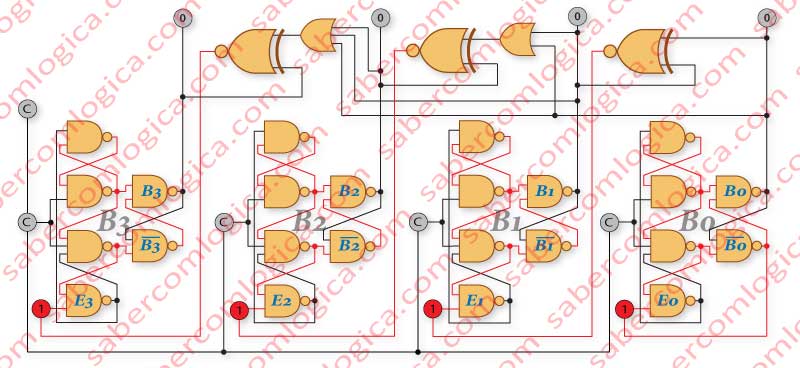
Figure 5 B0 and B1 are not both 0 and B2 is 0 or
- B0 and B1 are both 0 and B2 is 1;
-
- B2 is 1 every time in the preceding number:
- B0 and B1 are both 0 and B2 is 0 or
- B0 and B1 are not both 0 and B2 is 1.
This repeated condition of B0 e B1 not being both 0, or being both 0, matches the application of an OR operator to B0 and B1, which only returns 0 if both are 0. So, in other words, we can say that:
- E2 is 0 every time B0 OR B1 and B2 are different.
- E2 is 1 every time B0 OR B1 and B2 are equal.
This is the behavior of a XNOR gate. If both equal, it returns 1, if both are different, it returns 0.
So, if we connect B0 OR B1 and B2 to a XNOR gate, its output will have the value of the next B2. Let’s connect it to E2, and in the next Clock, the desired value will be memorized in B2.
E2 = (B0 OR B1) XNOR B2
Regarding B3, we will follow the same logical reasoning we did for B2 with the difference that now, at the OR gate inputs we must have B0, B1 and B2.
- E3 is 0 when B0 OR B1 OR B2 and B3 are different.
- E3 is 1 when B0 OR B1 OR B2 and B3 are equal.
In the same way, if we connect B0 OR B1 OR B2 and B3 to a XNOR gate its output will have the value of the next B3. Let’s connect it to E3, and in the next Clock, the desired value will be memorized in B3.
E3 = (B0 OR B1 OR B2) XNOR B3
In Figure 6, we have a simplified representation of a descending counter where we can verify its implementation ant operation during 4 iterations.
Frame I represents the starting point, with a stabilized situation, and the Clock at low. At the outputs of the Counter are the initial values of 1000(8). At the inputs of the Counter are the values resulting from the connections between the outputs and inputs, the value 0111(7), waiting for the next Clock to be memorized.
This is what will happen in Frame II, the first of the 4 represented iterations.
Frames III, IV and V represent the remaining 3 iterations which will take the counter to the final value 0100(4).
Conclusions
We ended up finding a universal standard behavior for ascending and descending evolution of a binary number based on their previous behavior, being allowed to conclude that:
In an iterative ascending evolution of a binary number, the value of its bit Bn has the following relationship with the preceding number:
- Bn is 0, whenever Bn-1 AND … AND B0 and Bn are equal in the preceding number, or in English, whenever in the preceding number:
- Bn-1 to B0 are not all 1, and Bn is 0 or
- Bn-1 to B0 are all 1, and Bn is 1.
- Bn is 1 whenever Bn-1 AND … AND B0 and Bn are different in the preceding number, or in English, whenever in the preceding number:
- Bn-1 to B0 are all 1, and Bn is 0 or
- Bn-1 to B0 are not all 1, and Bn is 1.
Resulting in the expression
En = (B0 AND … AND Bn-1) XOR Bn
In an iterative descending evolution of a binary number, the value of its bit Bn has the following relationship with the preceding number:
- Bn is 0, whenever Bn-1 OR … OR B0 and Bn are different in the preceding number, or in English, whenever in the preceding number:
- Bn-1 to B0 are not all 0, and Bn is 0 or
- Bn-1 to B0 are all 0, and Bn is 1.
- Bn is 1 whenever Bn-1 OR … OR B0 and Bn are equal in the preceding number, or in English, whenever in the preceding number:
- Bn-1 to B0 are all 0, and Bn is 0 or
- Bn-1 to B0 are not all 0, and Bn is 1.
Resulting in the expression
En = (B0 OR … OR Bn-1) XNOR Bn
Binary Counter with PL and Zero Detection
Counting circuits are rotary. This means that, when they reach one of the limits of what they can represent with its bit set, they restart counting at the opposite limit.
For instance, regarding a 4-bit counter, if it’s an ascending one, when it reaches 1111, it will resume at 0000 and if it’s a descending one, when it reaches 0000, it will resume at 1111.
Under this assumption, it’s a useful behavior in continuous counting of values equal to the maximum that can be represented by the bit set, since it sets an event, where they always count up to one of its limits, resuming at the opposite.
But, when we want to count to, or from, a value that we intend to define, we need to create instruments that allow us to inform the counter about that value. And we also need the counter to inform us when it finishes each count.
For this type of situation, we’ll have to introduce a Parallel Load circuit (PL). To know when the countdown ends, the descending counters have a zero detection circuit, meaning that the actual circuit detects when it reaches 0 and sends a signal to run PL, or any action that originated the count. Ex: increasing 1 second to the quartz watch we talked about after 1000 counting pulses and reloading 1000.
In Figure 7 we represent the logical circuit of a descending Binary Counter with Parallel Load and Zero Detection. This is the only circuit type (descending) that we will analyze.
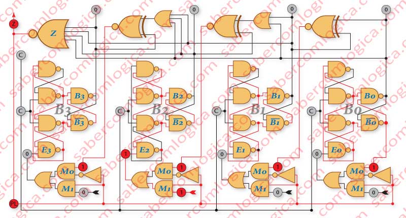
This circuit is at the end of a countdown, with PL active, thus having the MUX inputs M1 in E3,E2,E1,E0, ready to be memorized on the next Clock. Like the Shift Registers, the Parallel Load (PL) can be obtained by introducing a MUX 2-to-1, before each ETL. To each MUX input is connected:
- The order bit of the number to be uploaded.
- The value of the order bit to the counting sequence.
The Zero Detection (Z) can be obtained by connecting all the circuit outputs to a NOR gate, which will assume the value 1 (Z active at 1) when all the inputs are 0, or to an OR gate which will assume the value 0 (Z active at 0) when all the inputs are 0. When the counter reaches 0, if Z is connected to PL, and both have the same state when active, PL is activated and the counter loads the value at its inputs. Immediately afterwards, Z becomes inactive, and so does PL. The counter begins a new countdown starting from that value.
In this circuit we made PL active when 1, in order to verify, as we’ve said, that its state when active is defined by the way the connections are established inside the MUX.
In Figure 8, we have a set of frames illustrating the values of the circuit inputs and outputs, and the evolution of the connections along a countdown from 0100 (4) to 0000 (0), highlighting Parallel Load and Zero Detection.
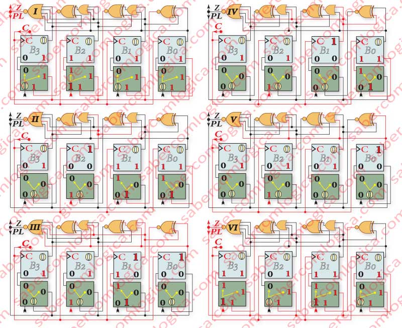
The values at the circuit outputs and the values selected by PL in the MUX are highlighted with greater digits. The bits’ order is the ETL’s order B3,B2,B1,B0.
The Clock will always be presented as high, and after is Rising Edge. This way, the circuit presents the state intended for that cycle, and the prepared state intended for the next cycle, waiting for the next Clock Rising Edge.
- Frame I – The circuit is in the same state as described for Figure 7.
- Frame II – At the Clock Rising Edge the values to be loaded, present in E3,E2,E1,E0, are memorized. The Parallel Load (PL) is executed.
Before a new Clock, Z e PL change to 0, as now the counter’s outputs are not all 0. Thus, the MUX’s gate M0, where the counting sequence number with bits 0011 (3) is connected to, is selected. That way those bits will stay at E3,E2,E1,E0, waiting for a new Clock to be memorized.
The bits of the loading number are present at the MUX’s M1 inputs, but they are ignored. - Frames III, IV and V – The circuit remains in its counting state until the value 0000 (0) is the next in the countdown, and is at E3,E2,E1,E0, waiting for the next Clock to be memorized.
- Frame VI – At the Clock’s Rising Edge, the counter reaches Zero, memorizing the value 0000(0).
After that Clock’s Edge, Z and PL change to 1. Thus, the MUX’s gate M1, where the number to load with bits 1010(10) is connected to, is selected. That way those bits will stay at E3,E2,E1,E0, waiting for a new Clock to be memorized. The zero detector tells anyone outside the circuit that this countdown reached Zero through its signal Z.
The Clock falls, but the values at the inputs and at the outputs, as well as the value of PL, stay stable and wait for a new Clock. There, a new countdown will begin, now starting from 1010(10). Notice the value 1111 at the MUX’s M0 inputs. If PL was not activated, the countdown would start there, the upper limit for a 4-bit number.