Binary Subtraction
Subtract one number from another is the same thing that adding it to its symmetrical. Thus if we want to subtract 37 from 65 we get the same result if we add to 65 the symmetrical of (+37), i.e., (-37).
65 – (+37) = 65 + (-37) = 28

In base 2 everything goes the same way. When we want to subtract one number from another, we establish its symmetrical and add the result to it.
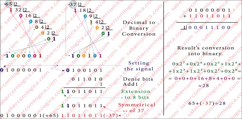
Let’s exemplify this operation in the graphic of Figure 1 step by step as indicated in its captions. In a first step the numbers 65 and 37 are converted into their unsigned binary representation. The number 65, now 1000001 is represented by 7 bits. Adding to it the sign 0 because it is positive, it will come to have 8 bits and thus being prepared for the operation, as
65 = 01000001
With the number 37, now 100101 we will have a lot more things to do. Adding the sign to it, 0 because it is positive it will come to have 7 bits, as 0100101. Then we deny its bits and add 1 to the result, getting 1011011. Finally we extend it to 8 bits thus being prepared for the operation as
(-37) = 11011011
Now we can do the binary addition of 65 and (-37) as we can see in Figure 1-14 . The final carry out of the operation has the value 1 but as it doesn’t fit in a 8 bits representation it is ignored. As we said we will deal with this question further on.
After all, we are dealing with addition and subtraction the same way, only with different assumptions.
Is it by any chance possible to identify a common pattern in both operations behavior that would allow us to use the same circuit for both purposes, just introducing some additional logic into the adder circuit?

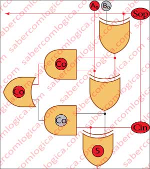
Let’s see and follow the description with Figure 2, where the circuit is materialized. First we have to bring to the adder the information about the kind of operation it will be doing, if its an addition or a subtraction. That can be done with a sign which we will call by Sop (sign of the operation). If it is a subtraction the bits of the second operand have to be denied, but only if it is a subtraction.
How are we going to tell the circuit if it denies or not the second operand bits? We are dealing with a circuit which does two types of operations, but only one in each moment.
Probably it won’t be very difficult to deny the bits. There’s a logical gate which does it for us. The XOR gate. Always 1 when different and 0 when equal. We will put one XOR gate per bit before the adder circuit, connecting the 2nd operand‘s bits to one of their inputs and the operation identifier sign Sop to the other input. Since Sop assumes the value 1 for subtraction, the XOR operator fulfills its function inverting (denying) the value of all the bits of the 2nd operand.
And when the operation is an addition?
In this case, Sop assumes the value 0 indicating addition, the XOR operator input with Sop will assume the value 0 and thus XOR will always return the value of the other input, the 2nd operand not denying its bits. If we connect these XOR gates output to the Adder circuit 2nd operand input, the denial of its bits for the subtraction, and only for the subtraction, is ensured.
But what we want there it’s not the 2nd operand’s denial but its symmetrical. In order to get it we have yet to add the value 1 to the denial. And now what?
We have to sum 1 to the first bit!
But, as the circuit is already adding the two zero-order bits of the operands, how do we put a 3rd bit over there?
If, instead of a partial adder for the first bit we use a full adder, we can introduce a further element to the sum in the form of a carry in. Yes, it’s possible.
But how do we tell our friend that it only uses this value when it is doing a subtraction?
Wait! We don’t need to say anything. The carry-in is always added . It’s its value which can be either 1 or 0. So we just have to connect it to Sop, the operation identifier, and thus the first carry in (Cin) assumes the value 1 if it’s doing a subtraction or 0 if it’s doing an addition. Ok! Now its complete!
We can ensure that the 2nd operand will always be represented by its symmetrical in a subtraction, and only for this operation.
Let’s put all this together and summarize:
- To each of the adder circuit 2nd operand input will be connected the XOR gate output whose inputs are the operation identifier sign Sop and the respective 2nd operand bit.
- If Sop is 0 (addition) the XOR gate will return the real value of the 2nd operand bit. If Sop is 1 (subtraction) the XOR gate will deny the 2nd operand bit.
- Sop being connected to Cin (the carry in of order 0 bit) adds 1 to the sum of order 0 bits when Sop is 1 (subtraction) and adds 0 when Sop is 0 (addition).
This is just what we pretended. When the operation is a subtraction the 2nd operand bits are denied and 1 is added to it, thus being converted in its symmetrical. When the operation is an addition the 2nd operand is used as it is.
We are going to add some graphics of this circuit, illustrating the various operations of addition and subtraction between the values 5 and 13, trying to cover all the possible significant addition and subtraction operations with these operands, which can be seen in Figure 4.

For certain operations with 5 and 13 in two’s complement, such as the sum 13+5=18, we need 6 bits (-32 to 31) to represent the result.
The numbers 5 and 13, represented with 4 bits when unsigned, need one more bit, the sign, for its two’s complement representation, so 5 bits.
Thus, we will use 6 bit logical circuits and extend the binary representation of 5 and 13 to 6 bits, as shown in the table in Figure 3.
Some important observations about the Frames of Figure 4 before we proceed:
- Sop is the operation identifier.
- Cin is the circuit’s do carry in, equal to Sop.
- The operands A and B are represented by the bits:
- A0 to A4 and SinA as A5.
- B0 to B4 and SinB as B5.
- SinA and SinB represent A and B signs.
- C0 to C5 represent the adder circuit 0 to 5 orderbits Cout or the Cin of the above order bits.
- S0 to S4 bits and S5 as Sign represent the result.
So, let’s proceed with the frames of Figure 4:

In Frame I we subtract (+5) from (+13).
This operation corresponds to the subtraction (Sop=1) of equal sign operands [(+13)-(+5)].
Actually what this circuit does is an addition. Being notified by the Sop sign (1) that the operation is a subtraction, it calculates the symmetrical of the 2nd operand and executes the operation
[(+13)+(-5)].
The result is 001000, or (+8) in decimal.

In Frame II we add (+13) with (+5).
This operation corresponds to the addition (Sop = 0) of equal sign operands [(+13)+(+5)].
The operation that the circuit executes is exactly the one which is identified. Being notified by the Sop sign (0) that the operation is an addition, it lets the second operand go through without any changes and executes the operation
[(+13)+(+5)].
The result is 010010, or (+18) in decimal.

In Frame III we add (+5) with (-13) .
This operation corresponds to the addition (Sop=0) of different sign operands [(-13)+(+5)].
Again, the operation that the circuit executes is exactly the one which is identified. Being notified by Sop (0) that the operation is an addition, it lets the 2nd operand go through without any changes and executes the operation
[(+13)+(+5)].
The result is 111000, or (-8) in decimal.

In Frame IV we subtract (+13) to (-5).
This operation corresponds to the subtraction (Sop = 1) off different sign operands [(-5)-(+13)].
Actually the operation that this circuit executes is an addition. Being notified by the Sop sign (1) that the operation is a subtraction, it calculates the symmetrical of the 2nd operand and executes the operation
[(-5)+(-13)]
The result is 001000, or (-18) in decimal.

In Frame V we add (-13) to (-5).
This operation corresponds to the addition (Sop = 0) of equal sign operands [(-5)-(+13)].
Actually the operation that this circuit executes is an addition. Being notified by the Sop sign (0) that the operation is an addition, it lets the 2nd operand go through without any changes and executes the operation
[(-5)+(-13)],
what matches exactly what was done in the previous frame. we start from two different situations to end in the same solution for the circuit. The result is 001000, or (-18) in decimal.
We verified in these 5 Frames the behavior of the adder/subtractor circuit in some different situations of addition and subtraction with different operand signs. The purpose was to illustrate how the operands are introduced in the circuit according to their sign and to the Sop value.
Let’s now address the frequently focused topic, the excess, which occurred in Frames II and IV. If we had not extended the circuit to 6 bits, the order 5 bit wouldn’t exist to absorb this excess. The generated situation, once not properly treated, would cause an error.
Look at Frame II. The final Carry Out of the circuit is 1, correct? But we ignored this carry Out. Why? However we said that there was an excess absorbed by the order 5 bit and the carry out was 0. How is that? We ignore it when 1 and valorize it when 0?
In this work we can do whatever we want. As we knew that the result of the operations we were going to execute could only fit into a 6 bit circuit, we created one.
Actually an 8 bits (e.g.) circuit is not extensible, it doesn’t know which operations it is going to perform and not even their result. But it has to be prepared to react correctly regarding all the possibilities it can face, always preventing the possibility of an error.
That’s just what we are going to see. How to detect, classify and manage the excess in binary operations. It’s an important matter, as if we don’t detect and correct the situation or stop the program issuing an error information, the error will propagate with unpredictable consequences.
