
Cache Mapping
When the CPU accesses the memory, it does it using the address that states the position of the record it pretends in the MM, not in Cache.
The CPU ignores the Cache. The Cache is organized in Blocks of several bytes (Cache lines). The locations in Cache have no correlation with the locations in the MM.
Therefore, we need to fetch in Cache with the byte address in the MM.
But how to do so? Rummaging? Going one by one?
For something like this it would probably have been better if the cache had never existed. Certainly it would take longer than going to the MM. We need the data to be provided promptly, with direct and simultaneous access to all the blocks, based on the elements of the addresses.
To do so, the Cache has a number of possible ways of organization, according to the method chosen to access it. In short, the cache will have to be mapped, i.e. we will need to elaborate a map with the addresses in the MM of the records it contains, just as George did. He wrote the addresses on the archive organized by room and bookcase. Then he wrote apart what records he had on each separator, or else he would have to go look one by one inside the tab.
Let’s now get some schemes made to show how the several methods of access are processed. These are merely illustrative, having nothing to do with the memory to which we have been creating circuitry.
In these schemes the Cache has 8 rows with 8 Bytes for each row. In the following frames we will see how to process in detail the access to the Cache. The fetch for a byte has to be made directly in hardware, with haste and at the first try, whatever the situation.
In these schemes the Cache has 8 rows with 8 Bytes for each row. In the following tables we will see how to process in detail the access to the Cache. The search for a byte has to be made directly in hardware, with haste and at the first try, whatever the situation.
Due to the reduced dimension we dispose for these schemes, the values of 1 and 0 are represented by red and gray circles, respectively.
Direct Mapping
The address sent by the CPU is decomposed in several parts.
From the bits with less weight are withdrawn the ones necessary to define the bytes position in the line or block. As the line has 8 bytes we’ll need 3 bits to identify the position of a byte in a block, i.e. the byte offset. In the same line with 8 bytes, the 3 last bits of a byte address go from 000 to 111. To this value we call offset or distance from the beginning of the line.
From the next bits in weight are withdrawn those necessary to represent the number of rows in cache. In this case 3 bits (8 rows) as well. This set is called the index and it defines the position of the block (row) that all records having those 3 bits occupy in Cache, being organized in sequence.
Thus, an address that has 010 100 as the value of the last 6 bits, will always be in the 3rd row (index=010) counting from bottom and will be the 5th (offset=100) of the line, counting from the left. We are organizing the Cache from bottom up and left to right.
Once found the row and the column in an immediate and direct manner, all there is left is to compare the label of the found byte with the same bits of the address (the remaining bits) and verify if they match. If everything goes as stated there is a Cache Hit and the value of the byte in that cache position is read or wrote.
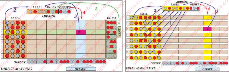
Looking at the respective frame, represented in Figure 4 (left), we see that:
- The arrow indicated with a 1 is pointing to the selection of the row, done using the value of the index in the address of the byte to be read or written.
- The arrow indicated with a 4 is pointing to the selection of the column, done using the value of the offset in the address of the byte to be read or written.
- The arrow indicated with a 2 is pointing to the comparison of the label in that row with the matching bytes in the address of the byte to be read or written.
- The arrow indicated with a 3, in case of Cache Hit, is pointing to the Byte in that Cache position, since it is the same that can be found on that address in the MM.
Nothing could be more simple and direct, although as expected, the picture is not all rosy.
Every address with the same 3 index bits always go to the same row. This means that, even if this cache row has a range of records that may be needed, if a jump makes it so you need to get an address that uses the same 3 index bits, this new Block is placed in the same row, replacing whatever was there before.
For the same reason, we can reach the end of a program with a range of cache rows unoccupied, if we never access addresses that have a certain combination of the index bits. And the more rows in the cache, the more the probability for this to happen.
Thereby, with this mapping the success rate substantially lowers. A simple mapping, with little hardware but with a lot of restrictions.
Full Associative Mapping
In this mapping, shown in Figure 4 (right), any line can occupy any position, as well as coexist in several cache Blocks whereas, in the last method, they would have to always be in the same row. We will only use the label and the offset. There is no index.
But in this way, won’t we have to look in all the lines to search the label we want?
Obviously not. It would take a huge amount of time compared to what is being looked for in a direct solution, one with an immediate response that requires no search. In cache, any solution has to be direct and made in hardware.
For this to be the case, we need to use a comparator for every cache row, introducing in each and simultaneously the value of the bits in the address corresponding to the label of the line which the comparison is made with.
So, if there exists in cache the address we fetch, the response will be immediate and the row identification will also be immediate. The column is identified in the same way as in the previous method, using the offset.
Therefore, the solution is also direct, but has the disadvantage of using a lot of hardware, this means a huge amount of transistors for each comparator and cache line, which will decrease the space for memory cells.
In the case of our mini Cache, it would be the ideal. But if we are talking about an 8 MB (8 million bytes) cache, we just can’t say the same.
The Full Associative Mapping is a mapping associated by sets of n Ways, where n represents the number of rows or blocks in Cache.
In our small Cache, a Full Associative Mapping would be an 8 Ways Set Associative Mapping, as many as its rows, one row for a set.
Set Associative Mapping
This mapping is made by the merging of the other methods. Each set is internally mapped in direct method and the sets are mapped in associative mapping.
In each set, any block that corresponds the set of address bits that identifies the index, has to always be on the same row. In the case of associative mapping using 2 ways, we will always have 2 rows that satisfy the search and whose label will be selected for a comparator, where it’s verified if its content matches with the address of the byte.
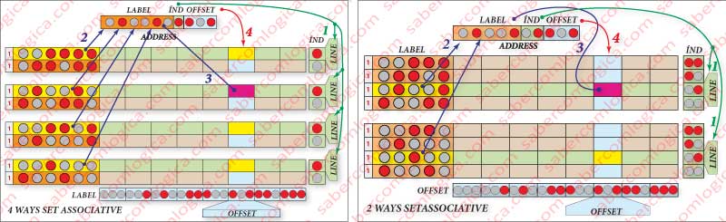
In our small Cache, the 2 ways correspond to 2 comparators and 4 rows by each way in direct mapping. Figure 5 (right) shows an illustrative picture of this kind of association.
Moving to an associative mapping of 4 ways, we will always have 4 rows that satisfy a search by index with a label that is selected for a comparator, where it is verified if its content matches with the address of the byte.
We have 4 sets of direct mapping that will be accessed in associative mapping.
In our small Cache, the 4 ways match to 4 comparators and 2 rows by way in direct mapping. We have 4 sets of direct mapping that will be accessed in associative mapping.
In our small Cache, the 4 ways correspond to 4 comparators and 2 rows by way in direct mapping. As it can be seen in Figure 5 (left), we have 4 groups of 2 lines, the index having 1 bit (with 1 bit you represent 2 lines). For each search, 4 labels (1) are selected (yellow background), which are then compared simultaneously, in 4 different comparators, with the corresponding address bits (2), resulting in cache hit or cache miss. In case of cache hit, it will be chosen the byte of the column correspondent to the offset (3).
The Set Associative Mapping is used in the Caches of CPU with high-end technology, built-in the chip itself, as we will see ahead in a study case.
Cache Blocks Substitution Methods
Whem a block needs to be written into Cache and its space is filled, it will be necessary to withdraw one block to create space to place it. For the Block substitution in cache we highlight 3 methods:
- FIFO (First In First Out) – the block that is there the longer is the first to leave.
- LRU (Least Recently Used) is the first to leave.
- Random – the computer randomly chooses the block.
In direct mapping Cache, the substitution method is very simple. Each block that comes in only has one place available for it. It is the place where you find the block defined by the index and offset bits.
It’s in the Associative Cache that we have to ask ourselves which is the block we want to substitute. In the Fully Associative we have to choose from all the blocks which is the block is want to substitute. In the Set Associative we have to choose from the block with the same index on the various sets, which we want to substitute. There is no choice since the mapping inside the sets is direct.
Due to the nowadays size of the Cache in any CPU, the most used approach is the Set Associative Cache.
If there still are some blocks with the valid bit low (0), then the choice for substitution will be done randomly between those.
The FIFO method may look as an efficient solution method, but it will not work in many cases, because a block can be in cache for a long time and be the most used one. Letting it go is a waste of time, since he will probably go get it next.
Its implementation is relatively simple in hardware. It’s enough that the blocks with the same index are kept in sets in a determined sequenced (e.g. Increasing order) and have a pointer in each set that defines the next block to be substituted.
It can be seen in Figure 8 (right side) an hypothesis of implementation of the FIFO in the Cache represented in Figure 8 (left side). The blocks are always written in sets in an increasing order from bottom up. A high bit (1) is always placed in the block to be written (the first one). For each writing, the high bit goes to the next block with the same index and the previous goes back to low (0). When it reaches the last block, it comes back to the first.
This way the high bit (1) works as a pointer that always points to the block to be written, which is the oldest one.
The LRU method is more complex, under a certain strictness factor dependent on the implementation, it may need a lot of support logic.
This support logic can go from a very soft solution, though with a small strictness factor, to a solution with a lot of logic due to a very high strictness factor, which means, there are a lot of transistors.
The Simple Solution, though with a lot less control and strictness, consists in using a control bit that, every time a block is accessed, is set to 0. Periodically, in an interval of a certain number of clock cycles, there will be a mechanism that sets all bits to 1. When a substitution is needed, the choice will be random over those that still have the bit set high (1).
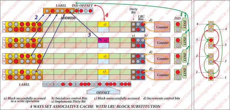
The Complex Solution, which allows more strictness in the choice, consists in the creation of a binary counter by set. You add to the cache blocks the necessary bits to represent all the ways of the cache, e.g. 2 bits for a 4 ways cache as in Figure 8 (left side) and you connect those bits to the set counter. For every access to the cache, every time the block in that way is not accessed, the control bit counter is increased and the bits from the accessed way block is reset to zero. Therefore, the more frequently accessed blocks have lower counters, even if they are the oldest in cache.
Of course this solution needs to have available the counter blocking mechanism when the counting reaches max value. As we know the counters are rotary and so they would return do 0, misrepresenting the strictness.
It must be also available a pointer that points, at every moment, to the block that has the substitution conditions. Let’s not forget that in Cache, everything has to be solved in hardware and directly find what is wanted. Cyclic searches are not accepted. Between the several blocks with the same counter, the pointer should always randomly point one of them.
Obviously the strictness of the choice increases with the number of bits of the counter and of the block dedicated to it. As well, the cost will exponentially increase.
Cache Writing Policy
There are two possible methods to write values in the Cache into the MM when necessary:
- Write Through -the values are written simultaneously in Cache and in the MM.
- Write Back – the values are written in Cache and in the MM only when the block is substituted.
To the purpose of this last method, the cache must have one more bit called the Dirty Bit. When the Dirty bit is 1, as we can see in Figure 8 (left side), it means that the values in the block have been changed thus needing to be written in the MM.
This last method can cause cache inconsistency problems, due to the existence of the DMA (Direct Memory Access) or direct memory access, which is provided to certain peripherals (e.g. HDD) and consists in the possibility that those peripherals directly access the MM. Thereby it can happen that a certain data of a Block found in cache is changed in the MM by other operations. When the writing of that block in the MM happens, the previous update will be gone, unless for each DMA access you look up and update all the Blocks that have the dirty bit high. Obviously, this method is slow.
In the first method the CPU is freed as soon as the value is written in cache, the remaining work being done by the MMU, which receives all the values that are written in cache with the respective addresses and does its registration in the MM. For that purpose, retention buffers with a waiting queue have been conceived for these caches, therefore, it is possible that the MMU keeps the writing values and goes updating them as the MM access is free.
When there are DMA access requests, before they are authorized it is guaranteed that the buffer is empty of records to be written in the MM, so granting its consistency.
If there is a Cache Miss during a write operation, it should always have the same treatment as a reading operation. The Block should be loaded in cache to be written the intended value, followed by the remaining procedure.