Intra AS9 Routing
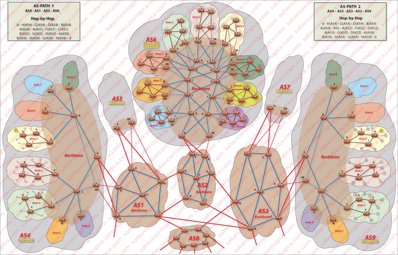
The aim of this Case Study is to know how the gateway router of subnet d of Area 1 of AS4 where is Geoge, who asks a page to a server that is on the subnet d of Area 1 of AS9, sees that server. We know how, because we see it in the picture. Let’s now see how the routers in AS4 know of its existence and how is the routing process until there.
We’ll use an imaginary case to exemplify the routing process in its various protocols during our journey, curiously in the inverse sense, in order to show how the router d of the Stub subnet of AS9, which serves the server we are looking for, does to get known to the router d of the Stub subnet of AS4, which serves George.
Let’s follow the description supporting us in Figure 1 which we introduce here again. Click or touch the image to open it in a new window and follow the description always seeing it.
We introduce here and again through Figure 2, the graphic representation of the organization and served addresses by NetByCabo, which we’ll use as case study for the steps that the routing process will follow until the AS9 border router, the part that we are going to describe in this article. Once again we want to make clear that the name NetByCabo was imagined by us and that any comparison with reality is pure coincidence.
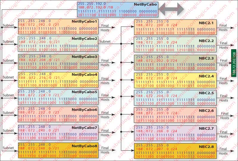
Let’s then start with the subnet d of Area 1 of AS9 and check how its address will be recorded in the successive routers until we reach George’s network. AS9 corresponds to ISP NetByCabo which has already been analyzed concerning addressing and that we will now be used again concerning routing.
Area Zones – NetByCabo 2 – OSPF Protocol
According to the graphic in Figure 1, subnet d, where is the server you intend to send a request to, has a subnet address block 188.72.202.0/24, i.e. 254 hosts (?) on the subnet defined by the first 24 bits of that address. Router d will present its network prefix as the addresses that it undertakes to deliver, what is reproduced in its routing table.
You said 254 hosts? But 8 bits define 256 decimal numbers. How is that?
Yes, 254 Hosts, as address 0 refers to the network itself and address 255 is a broadcast inside the network. Correct? Let’s go on.
The subnets represented with lowercase letters correspond to NBC x.y concessioned by NetByCabo x. Each of the eight NetByCabo x is an area that lives within the AS9, concessioned by NetByCabo.
The subnets NBC x.y (those in lowercase letters) are Stub Networks, i.e. all traffic that goes to it is designated to its hosts and all the traffic that comes out of it comes from its hosts. Each one presents to the outside as a subnet prefix, the set of addresses that it undertakes to deliver. Let’s start from there.
We join Figure 3, which shows how networks and subnetworks achievable by each router are displayed in its respective interfaces.
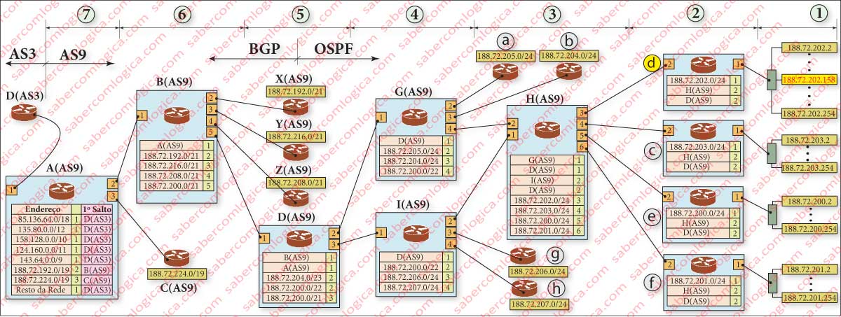
The table shown in each router must be seen as the view from inside the router, i.e. as if we were inside the router and we wrote on the table what we see through the door of each interface . The interfaces are numbered in shaded orange squares, the references to them in the table are shaded in green and what you can see through them, already aggregated, is rose shaded.
These elements are provided to its neighbors which, that way, get to know what they can see through their doors if they follow the path through them.
In the pink shaded area are represented the reachable subnets through each interface. Of course we are only interested in evaluating how the address of the subnet that interests us is presented by routes aggregation as we ascend in the hierarchy. When in the table is written the reference to a router ID, it means that this line will match the full range of addresses reachable through this interface and that router.
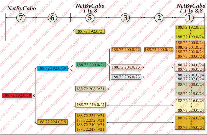
To better understand how route aggregation is done and when it can or can not be done, we put here together Figure 4. The numbers shown at the top of the two figures 3 and 4 with arrows delimiting spaces ,seeking to refer the various levels of increase in terms of alignments and routers, are matched in the two figures.
It’s shown in figure Figure 4 where the division between the protocols OSPF and BGP is, which is precisely at the Area border routers, i.e. where each NetByCabo x begins . Also indicated is the separation between AS3 and AS9.
The reading of all figures should be combined with that of Figure 1, in order to understand how the presentation of the network containing the server we are interested in evolves.
Let’s look at router H(AS9), which will provide the addresses of all routers that are before him (c, d, e) to the upper level network, presenting in turn to them what that network has to offer them through it . Each of these access routers has different routes, which will appear in the routing table of the H(AS9) in different interfaces, namely:
- Interface 1, through which we can see the router I(AS9) and specifically the way it displays the path to the client making the request.
- Interface 2, where you see the router G (AS9) and how the customer’s network is presented.
- Interface 3, where you see the aggregation of addresses which the router d undertakes to deliver.
- Interface 4, where we see the aggregation of addresses which the router c undertakes to deliver.
- Interface 5, where we can see the aggregation of addresses which the router e undertakes to deliver.
- Interface 6, where we can see the aggregation of addresses which the router f undertakes to deliver.
Route Aggregation
Router H(AS9), by sending its neighbor I(AS9) the status of its links, tells him that it knows how to get to 188.72. (200,201,202,203) .0/24, which he presents in binary form according to that shown in Figure 5.
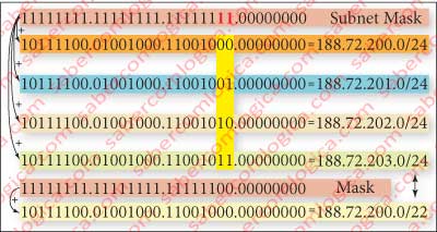
Each of the network address in decimal form is represented by its binary conversion associated with a binary mask. Notice the brown shaded area where the four network addresses meet the possible combinations of the two last bits of the mask.
Then they are representable by the same network binary address with these two last bits removed from the mask, through the network decimal address being represented by 188.72.200.0/22, as can be seen in this Figure 5.
The router I(AS9) places in its interface 2, the one who connects to H(AS9), the aggregation of the four routes presented by H(AS9) to its neighbors, exactly what it can see through that interface. When the packet with the address 188.72.202.158 (10111100 . 01001000 . 11001010 . 10011110) arrives at the router I(AS9), as its first 22 bits match those of the network address seen through interface 2 (188.72.200.0/22), it is forwarded that way, arriving to H(AS9) by following the road that connects to that interface. Once arrived to H(AS9), as its first 24 bits match those of the network address seen through interface 3 (188.72.202.0/24), it is forwarded to that interface, then reaching the router of Stub subnet d, which provides services to the host with the address 188.72.202.158.
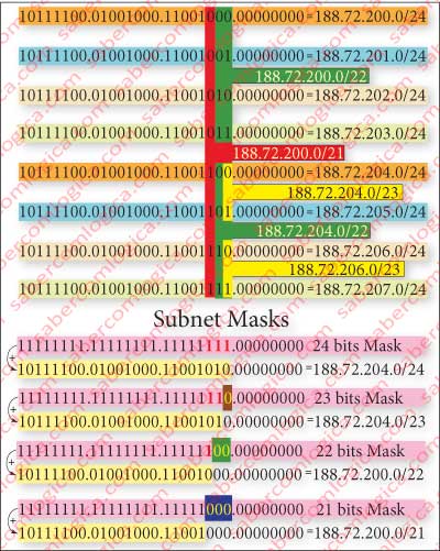
Let’s follow an example, this time using Figure 6 to see how the route aggregation is made in the router D(AS9) accordingly to the information received from its neighbors G (AS9) and I(AS9), in order to better understand how this works, through the analysis of the bits or digits of binary representation.
We start with the situation in which two addresses, 182.78.(205,204).0/24 are aggregated as 182.78.205.0/23, representing the two possible variations of the mask last bit. This is the value transmitted by router G(AS9) to its neighbor D(AS9), which sets 182.78.205.0/23 in its interface 2, the interface through which it sees it.
Let’s notice now the situation in which I(AS9) passes to its neighbor D(AS9) information about its knowledge. The router I(AS9) knows the network addresses 182.78.206.0/24 and 182.78.207.0/24. Normally they should be represented by D(AS9) in its interface 3 as 182.78.206.0/23, aggregation under the same address and a mask with one bit less . But, in that same interface 3, D(AS9) also acknowledges the network address 182.78.200.0/22, which is transmitted to it by I(SA9).
Its now time to apply the rule that we have already announced for routing under CIDR. D(SA9) has in its interface 2 and interface 3 the set of 4 possible variations of the network address 182.78.204.0/22 corresponding to the aggregation of the network addresses 182.78.204.0/23 and 182.78.204.0/23 respectively present in interface 2 and interface 3. The referred property of routing under CIDR consists in the fact that the route chosen to forward a packet is always the one in the table entries where the number of bits of the address matching with the network address for the 1 bits mask is bigger. Thus, D(SA9) can aggregate in interface 3 the network addresses 182.78.200.0/22 and 182.78.204.0/22 presenting them as 182.78.200.0/21. Inside this aggregation in interface 3 misses the set of network addresses 182.78.204.0/23 which is in interface 2, but no problem results of it because the addresses with 23 matching bits are forwarded to interface 2 and those where only 21 bits match are forwarded to interface 3.
Backbone AS9 – NetByCabo – iBGP
Now we will go out of Area 2 of AS9 and enter the Backbone zone of AS9. Note that A(AS9), in the table of the router D(AS9), is already visible from its interface 1 through router B(AS9). The visibility of AS border routers symbolized only by its name is used in our example, because we have only one border router in this AS. When this is not the case, BGP routing table will have to be presented in each one of them, because different border routers will present different routes for same destinations and backbone inner routers must be able to choose their preferred ones.
In our case, as all routes will have to go through A(AS9), we present only in A(AS9) the routing table with all the knowledge that AS3 through D(AS3) announces. D(AS3) is the first hop router for all those routes, i.e. the router to which all packets designated for those networks are directed.
You’ve surely noticed that, as shown in Figure 1, there is another border router AR(AS9), unlike we just said above. But both statements are true. AR(AS9) is a redundant router .
What is redundancy?
Redundancy
An AS must never be connected to the global network through one only router or link. In case of damage, cut of the link line or any other impediment, the whole AS9 (e.g.) would be without access to the global network.
Indeed, not only AS border routers but also the Area border routers and paths within Areas, should always have alternative paths. For this to happen, routers that have the same knowledge are provided at different stations. In AS9 we have considered a router with only that function, but in AS3 we used another existing border router for this purpose, which may have other functions beyond that.

For this reason we didn’t mention the router AR(AS9) as a communication path from AS9, because it is redundant to the router A(AS9).
Routers redundancy must also include the existence of two or more duplicated routers for the same function in the same station, in order to automatically replace anyone of them in case of malfunction.
All the routers that bypass information shall be provided with the existence of alternative paths. Imagine that failure is not in a router but in a whole station. Thus, duplicates would avail nothing, for they would be dead too and therefore all the networks they serve, which could be many.
In AS6 we tried to show how an entire network can be redundant, without having to create unique routers with redundant functions, taking advantage of those that already exist to service the network and changing the way they are interconnected. Notice how in the case illustrated in Figure 1, any router (or channel) can be switched off and the information continues to reach all the others.
Redundancy level, determined for each network or to a node of a network has to do with the tolerance allowed for the same.
Tolerance is defined by the system’s downtime per year, including its maintenance. The smaller the tolerance, the greater the redundancy. In addition with other factors that we omit here.
The degree of tolerance is measured by nines. As a curiosity, we put together the table in Figure 7, with the relationship between the classification by nines, the percentage of time that a system remains available and the maximum downtime per year.
For example, Google site has a rating that is between 4 and 5 nines, varying from country to country. Support systems that involve human life, will always be inside the largest scales, if not the greatest.
In AS4 and AS9 we intentionally did not use any redundancy, in order to turn easier the understanding of knowledge transfer between routers.
