
DHCP
DHCP is the acronym for Dynamic Host Configuration Protocol, or in people language, the way for someone who connects to the network to obtain an address. When we connect to the network we are nobody. Then a such Mr. DHCP comes and says: Hey, you look like a good guy and as you want to talk to the others i give you an address to live in, the123.231.123.231 (these little numbers mean Country, City, Street, Building and Apartment it it was between us).
Let’s see how this works.
There is a worldwide organization responsible for the registration and assignment of names and addresses, which is ICANN (Internet Corporation for Assigned Names and Numbers), which in turn delegates to the IANA (Internet Assigned Numbers Authority) the responsibility for assigning addresses.
IANA allocates blocks of addresses to 5 RIR (Regional Internet Registry):
- AfriNIC for Africa
- ARIN for USA and Canada
- APNIC for Central and South East Asia, Australia, New Zealand, Indonesia, Philippines and neighboring countries.
- LACNIC for South and Central America, and Caribbean
- RIPE for Europe, Middle East and Central Asia, and North America.
Each of these regional entities in turn allocates address blocks to ISPs and large direct customers of higher hierarchical level, which in turn will divide by lower levels of access ISPs, which will provide Internet access to end users.
Sometimes it happens that one single ISP can fulfill several layers. We’ll see this question when talking about routing.
We have seen with an elementary example how address blocks can be allocated and divided. And the end user, how does it get its address?
Normally the end user should get its address by direct allocation made by the administrator of its access ISP and stay with it forever. But it can’t be like that. IPv4 addresses are a short walk from exhaustion, and therefore rationalizing the assigned addresses.
Assigning addresses only to users who are at each moment connected to the network, e.g. a provider of an apartment complex with 10,000 hosts will probably be able to solve the situation with a block of 2,048 or 4,096 addresses.
Each time a terminal equipment is connected to an ISP it runs DHCP, which is an application layer protocol that allows it to obtain an IP address.
Then we’ll have a DHCP client, the equipment that connects to an ISP and a DNS server to give him what he wants. The DNS server is at the well known port 67 and the DHCP client at the well known port 68.
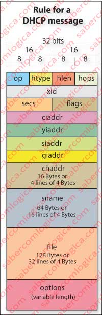
Let’s first look at Figure 1 with the rule for a DHCP message, more complex than the previous ones we have seen. The fields are defined as follows:
- op – code or message type – BOOTREQUEST = 1, BOOTREPLY = 2
- htype – hardware address type – e.g. ethernet = 1.
- hlen – hardware address length in bytes – 6 for Ethernet
- hops – Set to zero by client. Optionally used when a network uses a DHCP server on another network. In such cases there is a DHCP binding relay readdresses broadcast.
- xid – Transaction ID, chosen randomly by the client and used by client and server to associate messages exchanged between them.
- secs – Completed by the client and used to determine the elapsed time in seconds since the client began the process of acquiring or renewing the address.
- flags – The highest order bit is the one that sets the Broadcast (bit B). The remaining 15 bits should be set to zero, and are intended for future use.
- ciaddr – Client IP address. Is only populated if the client is in a state of BOUND, RENEW or REBINDING and can respond to ARP requests.
- yiaddr – ‘your’ (client) IP address.
- siaddr – address of next server to use in bootstrap; is sent in DHCPOFFER and DHCPACK messages by the server
- giaddr – Relay agent address (referred to in hops), if one exists.
- chaddr – Hardware address of the client.
- sname – Optional, is the name of the server host, which must end in null and fulfills the 64 Bytes. Inherited from BOOTP or Bootstrap Protocol, must be filled with zeros if not used.
- file – Boot file name. It should be generic or null in DHCPDISCOVER and must have the full path in DHCPOFFER. Must end in null and fill 128 bytes. Inherited from BOOTP or Bootstrap Protocol, must be filled with zeros if not used.
- options – Variable set of options to be used among those available for DHCP.
The fields that involve information Boot, BOOTP or Bootstrap Protocol, are intended for machines without hard disk, thus with no permanent memory, so they can find an IP address, a host server address on its network and a file name to be loaded into its memory and executed. We stay just for this information regarding this type of fields.
ARP, also found in the fields described before, is a query and response protocol at link layer (below this one) to translate IP addresses into hardware addresses (MAC Address), which we will discuss when we get to that layer.
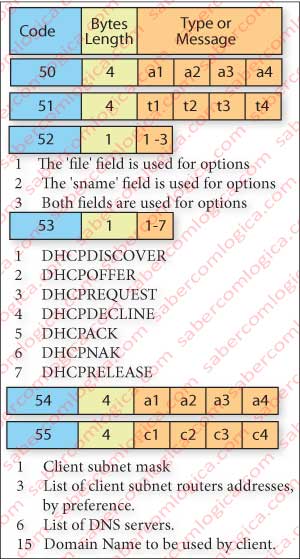
It’s in this last field “OPTIONS” that goes a description of what is desired in each message. So we’ll see what are some DHCP extension codes, as shown in Figure 2:
CODE 50 – This code is used by the client in the DHCPDISCOVER message to ask for a particular IP code to be assigned to it. The length of this field is 4 bytes.
CODE 51 – This code is used in the client request to ask for the address to be assigned for a certain period of time and by the server to communicate what that period of time is. Time is specified in seconds in a set of 4 bytes, this being the length of this option.
CODE 52 – This code is used by the server to state to the client that it is using the space of the server name (sname) and/or the space of the path of the boot file name (file), for the options space is not enough for them (overload). It has three possible types:
- The “file” field is being used for options.
- The “sname” field is being used for options.
- Both fields are being used for options.
CODE 53 – This code is used to identify the type of message in progress:
- DHCPDISCOVER – It’s a Client broadcast to locate available servers.
- DHCPOFFER – The server answers to the client with the offer of configuration parameters.
- DHCPREQUEST – From client to servers:
- Requesting the parameters offered by one of the servers and rejecting those of others, or
- Confirming the correction of a previously allocated address, for example after a system reboot, or
- Extending the duration time of a particular address assignment.
- DHCPDECLINE – From client to server indicating that the address is already in use.
- DHCPACK – From the server to the client to confirm the parameters offered and awarded.
- DHCPNAK – From server to client to inform error by incorrect choice of network or because the duration of the address assignment time expired.
- DHCPRELEASE – From client to the server to release the address before the assignment time expiration.
CODE 54 – It is through this option that the server indicates its address to the client in a DHCPOFFER message to be distinguish from other servers. It’s through this option too that the client indicates the selected offer in a DHCPREQUEST message. It can also be used in DHCPNAK and DHCPACK. The length of this option is 4 bytes.
CODE 55 – This option is used by the client to request specific configuration parameters. The list of required parameters is specified by the codes of the respective options, from which point out 4, as an example. The length field refers to the number of required parameters, one per byte. The parameters are required by their code, which is the one of the list that we were describing.
We are thus able to simulate the arrival of a customer to a network and its request for an address to the DHCP server.
Case Study – Request for an address
Let’s look at the client with the address that has been with us during this chapter. For now we know that he belongs to subnet NBC 2.3.
When the client gets connected, he doesn’t even know the address of its own network, far less the DNS server address.
So being, how can he connect others in the network? How to solve the problem?
Get an address through DHCP is an operation performed in 4 steps, being given the name DORA (Discovery, Offer, Request, Acknowledgement), corresponding to:
- IP Discovery when the client asks for an IP address,
- IP Lease Offer when the servers send offers for a specific period of time,
- IP Request when the client accepts an offer from one of the servers and requests for confirmation and
- IP Lease Acknowledgment when the chosen server confirms the assignment of the offered address for the specified period of time.
Lease is the period of time for which the address is assigned to that client.
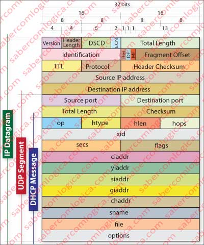
Figure 3 shows an IP datagram containing an UDP segment, which in turn contains a DHCP message, representing the rule of the datagram which is sent by the network layer on DHCP conversations.
Step 1 – IP Discovery
When the client gets connected to the network, shouts loudly for the DNS servers on its network:
“Hey guys, is there anyone out there with an address left for me?”
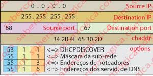
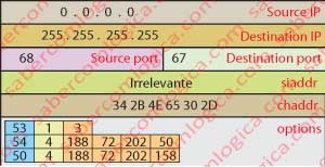
For this, it fills a DHCP message, puts it in a UDP segment and places the segment in an IP datagram, filling the fields accordingly to what it asks, as indicated in Figure 4.
Look at the options field populated with the desired information, the hardware address field also filled (the only one the client knows for now), source and destination ports in UDP segment and the datagram source (0.0.0.0 does not exist) and destination address (255.255.255.255 is a broadcast to the network, so to all DHCP servers on NBC 2.3).
Let’s see in detail the Options field, where the Client puts the questions to the Server:
53 – 1 – 1 <=> This is a DHCPDISCOVER message.
55 – 1 – 1 <=> What’s my Subnet Mask?
55 – 1 – 3 <=> What are the first router addresses for me, ordered by preference?
55 – 1 – 6 <=> What are the DNS server addresses for my network?
Any other fields that normally comprise the transmission of a packet, as referenced herein, will not be considered because they are not relevant to what we are discussing.
Step 2 – IP Lease Offer
Once the message is collected by one or more DNS servers on the network, they respond by saying:
“Hello there! I have here an address that I can lease for the indicated period, which I send you together with the information you asked for. I’m George”.
The DHCP message, as in Figure 5 and with the significant fields filled in, can be read as follows in the options:
53 – 1 – 2 <=> This is a DHCPOFFER message.
54 – 4 – 188.72.202.50 <=> Address of the DHCP server (e.g.), which makes this offer. His name is George.
51 – 4 – 41.200 <=> Period of allocation in seconds. Equal to 12 hours. Field length of 4 bytes.
1 – 4 – 255.255.255.0 <=> Response to the query 55 – 1 – 1, stating the Subnet mask.
3 – 20 – 5 addresses <=> Response to the query 55 – 1 – 3, sending 20 bytes with 5 routers addresses.
6 – 16 – 4 addresses <=> Response to the query 55 – 1 – 6, sending 16 bytes with 4 DNS servers addresses.
The fields yiaddr (proposed address 188.72.202.158), siaddr (address of next server to be irrelevant in our case) and chaddr (34 2B 4E 65 30 2D) are filled the message is placed into an UDP segment with destination port 68 and source port 67, and into an IP packet with a destination address of 255.255.255.255, and with its own source address. This message is yet sent in broadcast because the client has no address yet.
Step 3 – IP Request
The client receives the DHCPOFFER messages from one or more servers, chooses the offer he wants and echoes it in broadcast, so that all servers that have made offers know on whom the choice was focused:
“Thank’s to all of you. I’ve chosen the address that George sent me, so I ask George to confirm it to me.”
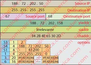
The message takes the options field filled as we can see in Figure 6 and with the meaning:
53 – 1 – 3 <=> This is a DHCPREQUEST message.
54 – 4 – 188.72.202.50 <=> Is the address of the DHCP server I’ve chosen, George as you see.
50 – 4 – 188.72.202.158 <=> Is the request for a specific address, precisely the one which was offered in yiaddr by DHCPOFFER.
The fields siaddr and chaddr are filled as they were already, but the field yiaddr goes blank.
The message is placed into an UDP segment with destination port 67 and source port 68 and into an IP datagram with destination address 255 255 255 255 and source address 0.0.0.0. The source address is invalid, because the client has yet no address.
Step 4 – IP Lease Acknowledgement
Once this message is received by the selected DHCP server, it sends a message to the client confirming that it accepts its choice, saying:
“Ok! I register and confirm your choice. I send you again the given address, the lease time and the information you asked for”.
The filled options fields meaning.
53 – 1 – 5 <=> This is a DHCPACK message.
54 – 4 – 188.72.202.50 <=> Confirms the address of the selected DHCP server.
51 – 4 – 41.200 <=> Confirms the period of allocation in seconds. Equal to 12 hours. Field length of 4 bytes.
1 – 4 – 255.255.255.0 <=> Confirms the response to the query 55 – 1 – 1, stating the Subnet mask.
3 – 20 – 5 addresses <=> Confirms the response to the query 55 – 1 – 3, with 5 the routers addresses.
6 – 16 – 4 addresses <=> Confirms the response to the query 55 – 1 – 6, with the 4 DNS servers addresses.
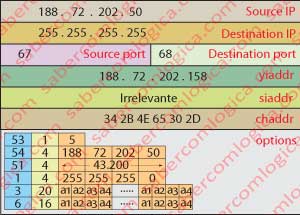
The message takes yiaddr, chaddr and siaddr fields filled yet as broadcast, as we can see in Figure 7.
The client interface and the routers are not yet configured with its new address, thus the message still be sent in broadcast by the server.
Once this message is received by the client the process of configuring IP address is completed, leaving it to configure its interface with the agreed parameters. Only after this message all the machines intervening in this process are configured to this address, by this meaning routers, DNS servers, the machine itself, and so on.
The World is informed about my new address.
I’m now finally integrated into the global network.
NAT
NAT is the acronym for Network Address Translation
Besides being a way, with one only public address, to give access to the public network to a maximum ceiling of about 60,000 users, NAT allows a private network of a dwelling, a building, a campus or a company to be hidden behind a router, i.e., none of the internal addresses of the private network is visible from the outside, nor it’s possible to get to them but through the NAT router.
Let’s try to understand why. In order to do it better let’s look into Figure 8, where we have considered a private network using private addresses with 5 hosts and a NAT router. The network is defined by the adress 192.168.1.0 and the internal interface of the router has the address 192.168.1.1
Although we will better develop this subject later, it´s good to clarify that a router has an interface for each I/O link with networks, subnetworks or other routers. In our case we have an interface facing the public network with a DHCP acquired IP which we admit to be 185.82.25.110 and another interface facing the private network with the address 192.168.1.1
The network internal distribution by different users is done by a switch, which can be combined with the router on the same equipment.
When an internal user of this private network intends to order the page that we’ve been using,
http://www.condominiopartners.pt/index.html
it fills the various headers we’ve seen so far placing in the source port, e.g. 4375, in destination port 80, in its private network address 192.168.1.5 and in the recipient’s address 188.72.202.158.
This packet can’t obviously go to the public side with an address of the private addresses spectrum, used exclusively by private networks and for each one separately understood. The message coming out of the user no 4 goes directly to the public network access router (Gateway).
When the NAT router receives this packet, it has to translate the address for it to be understood in the public side. To do this it has to open the packet and place its public address 183.82.25.110 in source address and place its own port, e.g. 6003 in the source port.
Then it places into a NAT table that it builds the relationship between the destination address and its source port in its internal system, and the source address and port of the user on the internal network.
Only by this description it stands clear that a NAT router must be able to reach the transport layer.
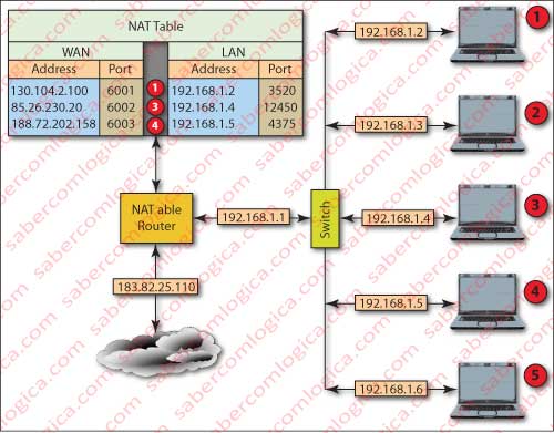
The NAT table illustrated in Figure 8 includes records for all users who have requests on the network.
This table will allow you to later redirect the response to the sender, since this response will bring as destination port the one you created for this transaction and as source address the one you have registered in your table.
The number of simultaneous connections that can keep a NAT router is regulated by the number of possible ports which are defined by a 16 bit binary number, thus being possible to be greater than 60,000.
Behind a NAT router can be a large private network, itself with routers and multiple subnets. Do not forget that a router has an IP address for each interface and each interface defines a subnet or a link for routing for other subnets.
Take for example the case of a company that has the granting of operating an extensive network of motorways, with subnets in all tolls, in office buildings, in operating concessioned stations, in a data center, in a center of road network management, etc.
All these subnets are at great distances from each other and are managed by the data center. This is a case of multiple LAN being connected by a WAN, where the communications are made over leased lines or other.
This entire set of private subnets of the same company can connect to the outside or even to each other through one only NAT router within the data center, with one only public address. All the multiple LAN and even WAN are routed through private addresses.
Advantages?
IANA will thank a lot to that organization. Only one IP adress for all those hosts.
From the outside of the company network nobody can see the addresses of the company hosts, which have private addresses. Only the address of the NAT router is publicly exposed.
Network security is much more efficient, because all traffic must pass through the same Firewall. An administrator only in one place, can control and enforce all constraints that he intends to the traffic that flows in, out and inside the company. Nobody can access from the outside any internal, host because their addresses are not usable externally without translation. Access to internal terminals as to go through NAT router.
Only security questions are enough to justify such an option, specially in an extremely promiscuous an incontrollable environment with thousands of hosts.
Well, it’s enough about addressing. Let’s talk now about routing.