
Executing the Program (Part 2)
As Instruções
Estamos a verificar graficamente a forma como a máquina executa com 0 e 1, através dos sinais de seleção, as instruções que lhe demos em C e em Assembly, encaminhando em cada ciclo de clock, os valores lógicos a partir dos Registadores sobre que atuarem e pelos circuitos que selecionarem, até às barreiras de fim de instrução, de novo os Registadores.
Em cada um dos gráficos poderemos visualizar os valores nos Registadores e na ULA bem como os circuitos intervenientes na UCP Op (operação máquina) referida. Acabámos o artigo anterior analisando como vai ser executada em Assembly a 4ª instrução C do programa que criámos e estamos a executar dentro da UCP.
4ª Instrução C
Assembly Line 8 – CPU Op 4
CP 2

represented in Figure 22. To this Assembly instruction corresponds the machine code instruction
100100000010
and the CPU Operation 4.
The PC points to the IM address 00000100 (4), where it can find the instruction to be ran.
This instruction can be typified as CP value.
Its Opcode generates the following control signals:
- DEFB which is 0, selecting the constant as the ALU 2nd operand .
- DEFALU which is 11, choosing the compare operation from the ALU.
- The ALU 1st operand comes from RegA, where it is already memorized. The ALU 2nd operand comes from the instruction constant routed by DEFB.
Both they are propagated inside the ALU where the selected operation is executed, setting in its parallel outputs the state of the bits Ig and R after the comparison is made.
This instruction sets the constant value in the ALU 1st Op. (Blue line), sets the RegA value in the ALU 2nd Op. (Violet line), compares both values and sets thee results R and Ig into RegALU (Green line) and increments the PC (Black line).
We recommend reading what we’ve written about the Comparator in the Chapter “Arithmetic and Logic operations“. The operand A from that circuit represents the ALU 1st operand (RegA) and the operand B represents the ALU 2nd operand (constant). As we’ve seen there:
- If R = 1 then A ≥ B.
- If R = 0 then A < B.
- If Ig = 1 then A = B.
- If Ig = 0 then A ≠ B.
This operation is accomplished when the values of Ig and R are set at the input of RegALU, as the evaluation of the results will only be done during the next machine operation. This instruction only compares two values.
Assembly Line 9 – CPU Op 5
JPM Fim
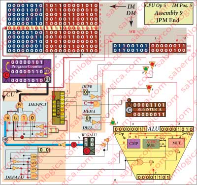
represented in Figure23. To this Assembly instruction corresponds the machine code instruction
111100001010
and the CPU Operation 5.
The PC points to the IM address 00000101 (5), where it can find the instruction to be ran.
This instruction can be typified as JPM value.
The decoded Opcode generates the control signal DEFPCI with the value 11, thus selecting in the MUXPCI the value of ¬R set at the previous instruction and now assigned to PL. When PL is 1 the PC jumps to the address provided by the constant (its value is parallel loaded), but while PL is 0 the address is incremented.
This instruction sets the value of ¬R (0) at the active input of the MUX DEFPLI (Blue line). Based in this value, the information about PL (0) is sent to the PC (Black line), which increments.
Here is where the decision about the Conditional Jump is taken. The condition is that A (RegA) is Minus than B (constant). That happens when R is 0, thus ¬R is 1 and PL is 1. But A (RegA) was compared with B (constant) in the previous instruction and the value of R was set there.
Yes, we said just that, the comparison was made with the value of constant in the previous instruction.
This is where RegALU acts. The values of Ig and R have to be preserved from that previous instruction until this one. During this instruction their value will be undefined, once they depend on the values in the meanwhile propagated to the ALU operands, now being compared. With RegULA, we don’t need to be worried, as the Ig and R previously set values are now protected from those changes in its outputs.
Assembly Line 10 – CPU Op 6
MUL [Fctr]
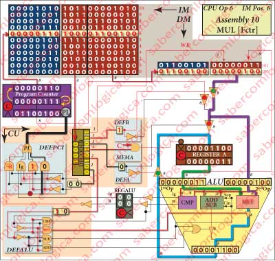
represented in Figure 24. To this Assembly instruction corresponds the machine code instruction
100001100100
and the CPU Operation 6.
The PC points to the IM address 00000110 (6), where it can find the instruction to be ran.
This instruction can be typified as MUL [address].
The decoding of the Opcode generates the following control signals:
- DEFB which is 1, selecting and routing the value in the DM position whose address is defined by the constant, coincident with [Fctr]. This value is immediately set at the ALU 2nd operand, as DEFB output is directly connected to it.
- DEFALU which is 10, choosing the multiplication in the ALU.
- DEFA which is 0, selecting and routing the result in the ALU to RegA.
- MEMA which is 1, memorizing in RegA the ALU operation result, routed to it by DEFA.
The ALU 1st operand comes from RegA, where is memorized the same value as in [Temp].
The ALU 2nd operand comes from the position of MD whose address is designated by the constant of the instruction, which is the [Fctr] position.
Both they propagate inside the ALU, where the multiplication is executed with them, being the result set at its output. This result propagates to RegA, where it is memorized when the Clock falls.
During this instruction 5 different actions are executed:
- Read the instruction from the IM.
- Decode the Opcode.
- Read from DM the ALU 2nd operand.
- Multiply in the ALU, the value in [Temp] by the value in [Fctr].
- Write the result in RegA.
- Increment the PC.
This instruction transfers a value in MD to the ALU 2nd Op (Violet line), the value in RegA to the ALU 1st Op (Green line), multiplies the two values setting the result in RegA (Blue line) and increments the PC (Black line).
Now, the value of the variable factorial representing the calculation of the N factorial until this iteration is memorized in RegA.
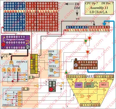 Assembly Line 11 – CPU Op 7
LD [Fctr],A
represented in Figure 1-25. To this Assembly instruction corresponds the machine code instruction
001001100100
and the CPU Operation 7.
The PC points to the IM address 00000111 (7), where it can find the instruction to be ran.
This instruction can be typified as LD [address],A.
The Opcode of this instruction defines WR as active (0), allowing the value memorized in RegA to be written in the DM position ([Fctr]) whose address is defined by the constant.
This instruction saves in the DM the value in RegA (Blue line) and increments the PC (Black line).
The value of factorial is now updated in DM.
Assembly Line 12 – CPU Op 8
LD A,[Temp]
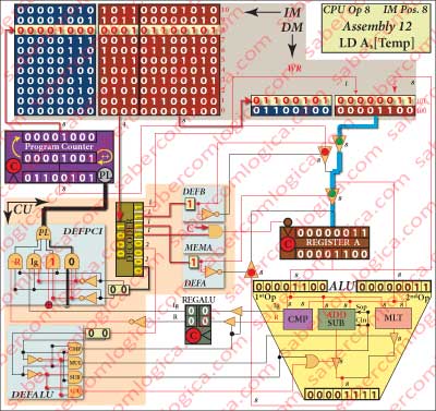
represented in Figure 1-26. To this Assembly instruction corresponds the machine code instruction
000101100101
and the CPU Operation 8.
The PC points to the IM address 00001000 (8), where it can find the instruction to be ran.
This instruction can be typified as LD A,[address].
The decoding of the Opcode generates the following control signals:
- DEFB which is 1, selecting and routing the value in the DM position whose address is defined by the constant and coincident with [Fctr].
- DEFA which is 1, selecting and routing the value coming from DEFB to RegA.
- MEMA which is 1, memorizing in RegA the value routed to it by DEFA, which is the value of the variable temporary.
This instruction reads the value of temporary from DM and sets it in RegA (Blue line) and increments the PC (Black line).
Assembly Line 13 – CPU Op 9
JP Repeat

represented in Figure 1-27. To this Assembly instruction corresponds the machine code instruction101100000010
and the CPU Operation 9.
The PC points to the IM address 00001001 (9), where it can find the instruction to be ran.
This instruction can be typified as JP value.
The decoding of the Opcode generates the control signal DEFPCI with the value 01, selecting the value 1 in DEFPCI thus assigned to PL. When PL is 1 the PC jumps to the address designated by constant (loads in parallel its value), which is the value of the label Repeat.
This instruction, forcing PL to 1(Red line), implies an unconditional jump to the Assembly line with the label Repeat.
One new iteration is going to start at line 6 of the Assembly program.
From now on the graphics representing the CPU operations are identical to those referred until now, being different only in the values we can see in the frames of DM, RegA and ALU.
We decided, for each new operation, to refer to the previous graphic and present a reduced representation referring to the frames with the values and to the main lines of the operation.
When this new iteration begins we have the following situations for the variables:
- factorial as the value 12 and is kept in the DM.
- temporary as the value 3, is kept in the DM and is memorized in RegA.
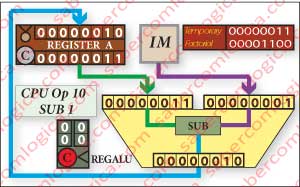 Assembly Line 6 – CPU Op 10
SUB 1
represented before in Figure 20 now in Figure 28
with the machine code 101100000010.
The value in RegA is set in the ALU 1st Op (Blue line). The value of the constant is set in the ALU 2nd Op (Violet line). The subtraction between these two values is made and its result (2) is memorized in RegA (Green line). The variable temporary has now the value 2 and is in RegA.
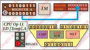 Assembly Line 7 – CPU Op 11
Load [Temp],A
represented before in Figure 21 now in Figure 29
with the machine code 001001100101.
The variable temporary (2) is saved in the DM (Blue line), as its value in RegA is going to be used and replaced in the next operations.
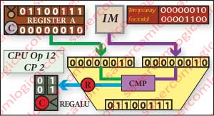 Assembly Line 8 – CPU Op 12
CP 2
represented before in Figure 1-22 now in Figure 30
with the machine code 100100000010.
The value of the variable temporary (2) still in RegA is set in the ALU 1st Op (Green line). The value of the constant (2) is set in the ALU 2nd Op (Violet line). The comparison between the two values is made and the results R (1) and Ig (1) are set in the input of RegALU (Blue line).
In this operation the CPU verified that temporary is not yet less than 2.
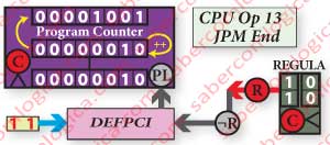 Assembly Line 9 – CPU Op 13
JPM End
represented before in Figure 1-23 now in Figure 31
with the machine code 100100000010.
The value R is memorized in RegALU and sent to the MUX (Red + Grey lines) where the signal DEFPCI is forcing a conditional jump (Blue line) according to the value of R.
AS temporary is not yet less than 2, the PC increments.
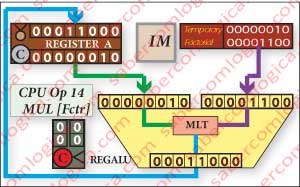 Assembly Line 10 – CPU Op 14
MUL [Fctr]
represented before in Figure 1-24 now in Figure 32
with the machine code 100001100100.
The value of factorial (12) in the DM is set in the ALU 2nd Op (Violet line). The value of temporary (2), yet in RegA, is set in the ALU 1st Op (Green line). The multiplication between the two values is made and its result set in RegA (Blue line).
The result is the new value for factorial (24) for this iteration of its calculation.
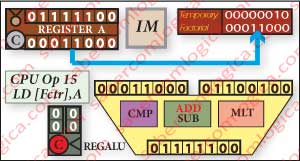 Assembly Line 11 – CPU Op 15
LD [Fctr],A
represented before in Figure 1-25 now in Figure 33
with the machine code 001001100100.
The value of factorial memorized in RegA is saved in the DM (Blue line), representing the 4 factorial calculation until this iteration.
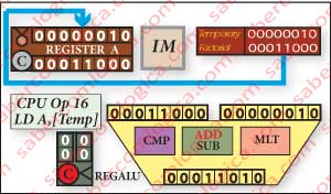 Assembly Line 12 – CPU Op 16
LD A,[Temp]
represented before in Figure 1-26 now in Figure 34
with the machine code 000101100101.
The value of temporary is read from the DM and replaced into RegA, in order for the calculation to proceed (Blue line).
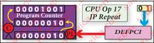 Assembly Line 13 – CPU Op 17
JP Repeat
represented before in Figure 1-27 now in Figure 35
with the machine code 101100000010.
DEFPCI signal forces in its MUX (Blue line) the active (1) input. So, PL is set to 1 (Red line), generating an unconditional jump to the address (Repeat) provided by the constant.
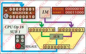 Assembly Line 6 – CPU Op 18
SUB 1
represented before in Figure 1-20 now in Figure 36
with the machine code 101100000010.
The value in RegA is set in the ALU 1st Op (Green line). The value of the constant is set in the ALU 2nd Op (Violet line). The subtraction between these two values is made and its result (1) is memorized in RegA (Blue line).
The variable temporary has now the value 1 and is memorized in RegA.
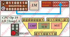 Assembly Line 7 – CPU Op 19
Load [Temp],A
represented before in Figure 1-21 now in Figure 37
with the machine code 001001100101.
The variable temporary (1) is saved in the DM (Blue line), as its value in RegA is going to be used and replaced in the next operations.
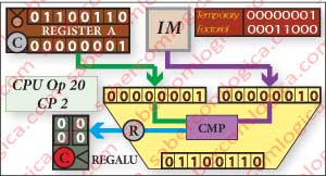 Assembly Line 8 – CPU Op 20
CP 2
represented before in Figure 1-22 now in Figure 38
with the machine code 100100000010.
The value of the variable temporary (1) still in RegA is set in the ALU 1st Op (Green line). The value of the constant (2) is set in the ALU 2nd Op (Violet line). The comparison between the two values is made and the results R (0) and Ig (0) are set in the input of RegALU (Blue line).
In this operation the CPU verified that temporary is now less than 2.
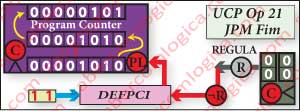 Assembly Line 9 – CPU Op 21
JPM End
represented before in Figure 1-23 now in Figure 39
with the machine code 100100000010.
The value R is memorized in RegALU and sent to the MUX (Grey + Red lines) where the signal DEFPCI is forcing a conditional jump (Blue line) according to the value of R.
As temporary is less than 2, the PC loads the value of the address (End) provided by the constant.
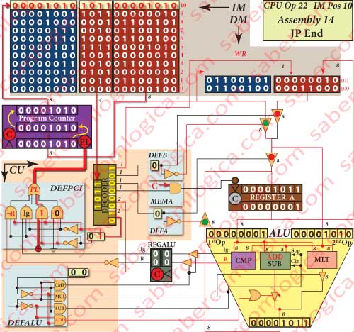 Assembly Line 14 – CPU Op 22
JP Fim
represented in Figure 1-27. To this Assembly instruction corresponds the machine code instruction
101100001010
and the CPU Operation 22.
t’s an unconditional jump instruction, as DEFPCI is 01, selecting its MUX input connected to power, thus always 1.
The jump is performed through the load of the address provided by the constant, which for this instruction is its own address in the IM. So this instruction forces a jump to itself.
In each clock cycle the PC loads the address for this instruction as the address for the next instruction. The CPU is in an infinite loop of Fetch, Decoding and Execution, until the Operating System takes hold of the situation and puts another program in its place.
Conclusion
And so we have reached the end of the little program that we used to illustrate the operation of a CPU. The value of 4 factorial is kept in the position [Fctr] of the DM as the variable factorial.
fatorial = [Fctr] = 24
One CPU where the IM had 11 rows, the DM had 2 rows and both where treated as circuits part of the CPU core. The IM had a word width different from the DM and the CPU cycle of Fetch, Decode and Execute for an instruction where fulfilled within the same clock cycle.
Obviously such CPU has not a real application. But it was good enough to understand how the abstraction is converted into reality within a CPU, how the instructions of a program are fulfilled by different interconnections of the CPU circuits obtained through the control signals.
now we are going to superficially analyze a last generation CPU, as deeply as our knowledge and the access to informations about its operation allow us to. From now on we will continue using the same CPU as case study for situations where the comparison with a real situation can be useful to our purpose.