
Executing the Program
The Decoder and the Control Signals

In Figure 17 the small numbers near the several lines designate the number of bit lines each one represents. The lines referring to the control signals resulting from the Opcode decoding, identified by numbers inside yellow bubbles, mean what we are going to refer next. The reference to the type of line representing those signals when active to 1, active to 0 or inactive (active or inactive means with or without relevance for the instruction) has to do with the graphics in the figures which are going to be with us during the several steps of the program execution.
- DEFPCI (2 bits) – This signal is active for all the instructions. The line representing it will be black shadowed bold (—) when the counter is incremented (00) and in red shadowed bold (—) when a jump is to be performed, i.e. the counter is parallel loaded (01,10,11).
- DEFALU (2 bits) – Is represented in red shadowed bold (—) when this instruction performs an ALU operation. When not, its representation will be in thin red (—) .
- MEMA (1 bit) – Is represented in red shadowed bold (—) when active and in thin black ( ) when inactive.
- DEFA (1 bit) – Is represented in red shadowed bold (—) when active at 1 , in black shadowed bold (—) when active at 0 and in thin black (—) when inactive.
- DEFB (1 bit) – Is represented likewise than the previous.
- WR (1 bit) – Is represented in black shadowed bold (—) when active and in thin red (—) when inactive.
We consider that, because it’s their natural state, to the values 00 for DEFPCI (increments), 1 for WR (doesn’t write in the DM) and 0 for MEMA (doesn’t write in RegA), we won’t mention them.
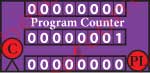
Regarding the PC (Program Counter) we want to make the annotations supported in Figure 17a:
- Line above -Contains the address in the IM of the running instruction
- Middle Line – Contains the address in the IM of the next instruction to be executed, coming from an increment or from a parallel load.
- Line Below – Contains the address in the IM for the parallel load, if such is defined by DEFPCI.
The Instructions
We are going to graphically verify the way how the CPU executes with 0 and 1 and through the control signals the instructions that we gave it in C and in Assembly, routing in each clock cycle the logical values resulting from their action over the Registers through the selected circuits, until they reach the end of instruction barriers, again the Registers.
In each one of the graphics we can visualize the values in the Registers and in the ALU as well as the lines affecting the referenced CPU Op (CPU operation).
1st Instruction C
In C we assign the value 4 to the symbolic constant N with the instruction
#define N 4
In Assembly we do the same with the directive
N EQU 4
Assembly Line 1 – Directive
N EQU 4.
When interpreting this directive the Assembler, will set the value 00000100 to all the constants in the machine code for the instructions which refer N, as we can see in the IM position 0 in Figure 18. Because this directive doesn’t generate machine code there’s no room for a CPU Op.
2nd Instruction C
int factorial = N;
With this instruction in C we assign the value N to the variable factorial with an integer type.
As we referred in the introduction we’ve made to C, with this instruction the compiler allocates a space in the DM for that variable, renames it with its position in the DM and saves its initial value there. So, in Assembly we execute this C instruction with 3 instructions, one of them being a directive.
Fctr EQU 100
assigning the value 100 to the symbolic constant Fctr.
LD A,N
loading into RegA the value of the constant N.
LD [Fctr],A
setting at the address [Fctr] from DM the value in RegA, thus the value of N.
Assembly Line 2 – Directive
Fctr EQU 100
When interpreting this directive the Assembler, will set the value 01100100 to all the constants in the machine code for the instructions which refer factorial, as we can see in the IM positions 1, 6 and 7 in Figure 18.
The variable factorial, whose name was given to it in C has not the right to be treated like that by the CPU. It will be treated as a position in the DM to which the address Fctr is assigned and is renamed as a pointer [Fctr] to that position. [Fctr] points to the position in the DM which will contain the value of factorial during the calculation of the N(4) factorial.
Because this directive doesn’t generate machine code there’s no room for a CPU Op.
Assembly Line 4 – CPU Op 0
LD A,N
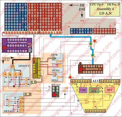
represented in Figure 18. To this Assembly instruction corresponds the machine code instruction
000000000100
and the CPU Operation 0.
The Program Counter (PC) points to the IM address 00000000, where it can find the instruction to be ran.
This instruction can be typified as LD A,Valor.
Its Opcode is decided into the necessary control signals to route and load in RegA the constant 00000100 defined in the instruction. This instruction is affected in concrete by:
- DEFB which is 0 and selects the constant in IM.
- DEFA which is 1 and selects the DEMUX B output, the constant in this case.
- MEMA which is 1 and memorizes in RegA the output of the DEMUX A, the constant in this case.
This instruction sets in the RegA the value of N designated by the constant, (Blue line) and increments PC (Black line).
This value will only be shown in RegA in the next operation frame, as it is memorized when the clock falls and we are representing the situation with the clock high.
Assembly Line 5 – CPU Op 1
LD [Fctr],A
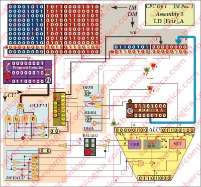
represented in Figure 19. To this Assembly instruction corresponds the machine code instruction
001001100100
and the CPU Operation 1.
The PC points to the IM address 00000001, where it can find the instruction to be ran.
This instruction can be typified as LD [address],A.
The Opcode of this instruction defines WR as active (0), allowing the value memorized in RegA (N) to be written in the DM position whose address is defined by the constant, coincident with [Fctr].
This instruction saves the value in RegA into the DM (Blue line) and increments the PC (Black line).
The 2nd instruction C is completed. One space in DM is defined for the variable factorial and the value N was assigned to it. For the CPU its name is now [Fctr].
3rd instruction C
int temporary = N-1;
With this C instruction the value N-1 is assigned to the variable temporary. For the same reasons we’ve referred to the previous instruction C, in Assembly we execute it with 3 instructions, one of them being a directive.
Fctr EQU 101
assigning the value 101 to the symbolic constant Temp.
SUB 1
subtracting 1 to the value in RegA. It’s the value of N which is there, coming from the previous instruction.
LD [Temp],A
setting at the address [Temp] from DM the value in RegA, thus the value of N-1.
Assembly Line 3 – Directive
Temp EQU 100
The Assembler sets the value 01100101 to all the constants in the machine code for the instructions which refer temporary, as we can see in the IM positions 3 and 8 in Figures 18 or 19.
The variable named temporary in C, is now a position in the DM with the address Temp and is renamed as a pointer [Temp] to that position.
As an Assembly EQU directive doesn’t generate machine code there’s no room for a CPU Op.
Assembly Line 6 – CPU Op 2
SUB 1
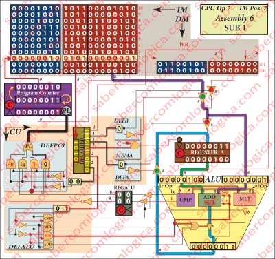
represented in Figure 20. To this Assembly instruction corresponds the machine code instruction
010100000001
and the CPU Operation 2.
The PC points to the IM address 00000010, where it can find the instruction to be ran.
This instruction can be typified as SUB, Valor.
Its Opcode generates the following control signals:
- DEFB which is 0, chooses the constant which becomes the ALU 2nd operand.
- DEFA which is 0, chooses the result of the subtraction made in the ALU to set in the RegA input.
- MEMA which is 1, memorizes in RegA the value chosen by DEFA to its input, the subtraction result.
- DEFALU which is 01, chooses the subtraction to be executed in the ALU.
The ALU 1st operand comes from RegA where the same value as in [Temp] is memorized. The ALU 2nd operand is the constant (1). Both they propagate inside the ALU, where the subtraction is executed with them, being its result propagated to RegA, where it will be memorized when the Clock falls.
During this instruction several different actions are executed:
- Read the instruction from the IM.
- Decode the Opcode.
- Subtract 1 to the value in RegA in the ALU.
- Write the result in RegA.
- Increment the PC.
The variable temporary having its value already decremented is now memorized in RegA.
This instruction sets the constant value in the ALU 1st Op. (Violet line), sets the RegA value in the ALU 2nd Op. (Green line), subtracts both values and sets the result into RegA (Blue line) and increments the PC (Black line).
Micro Operations (Micro-Ops or μOPS)
The several actions we’ve referred that are executed within the same machine code instruction are designed by micro operations or micro-ops or μops in a real CPU. The μops are the most basic operations, executed over the visible registers of the CPU architecture. These μops are executed according to the interpretation of the control signals resulting from the opcode decoding. The μops are atomic operations,i.e. not decomposable into other operations and their execution is to be made in one clock cycle (what doesn’t mean that its result will be found in one clock cycle).
For our CPU we’ve named them as actions from a same opcode because they are all executed within the same clock cycle and within the same elemental closed circuit, in order to turn this description easier to understand. But reality is not like this. An Opcode is decomposable in several μops or machine operations. Each μop may probably correspond to each of the mentioned actions.
We are now establishing the association between those actions of an opcode and the μops in order to introduce this concept which will be used in the study of a real CPU we’ll do further on. There we’ll see in further detail what they are and why to separate them.
Assembly Line 7 – CPU Op 3
LD [Temp],A
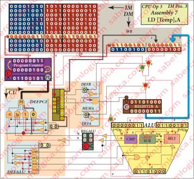
represented in Figure 21. To this Assembly instruction corresponds the machine code instruction
001001100101
and the CPU Operation 3.
The PC points to the IM address 00000011 (3), where it can find the instruction to be ran.
This instruction can be typified as LD [address],A.
The Opcode of this instruction defines WR as active (0), allowing the value memorized in RegA to be written in the MD in its position whose address is defined by the constant of the instruction.
With this instruction the value of the variable temporary is saved in the DM position [Temp]. Notice that this value is equal to factorial minus 1, thus the next value to multiply factorial in the calculation.
This instruction saves the value in RegA into the DM (Blue line) and increments PC (Black line).
The 3rd instruction C is completed. Another space in DM was defined for the variable temporary and the value N-1 was assigned to it. For the CPU its name is now [Temp].
4th Instruction C
In C we execute a loop, as already described in the introduction we made
while (temporary ≥ 2){
factorial = factorial*temporary;
temporary –;}
In Assembly we do the same with the set of instructions inside the program iterative cycle, beginning at the Repeat label and ending at the instruction JP Repeat.
SUB 1
LD [Temp],A
CP 2
JPM Fim
MUL [Fctr]
LD [Fctr],A
LD A,[Temp]
JP Repete
It’s not always possible to get a match between C and Assembly instructions blocks. That depends on the compiler and, in this case, on the way the Assembly program was conceived.
The first two instructions of this cycle should come at the end of it, in order to get that match. But they have just been executed to fulfill the previous C instruction.
We could always include them again in the Assembly program, at the end of the iterative cycle and change the beginning of the cycle (the Repeat label) to the line with the instruction CP 2. We would obtain the same effect, we would get a match between program blocks and we would all be very happy. But we would unnecessarily repeat Assembly instructions, what we don’t think to be a correct solution in terms of Assembly program. We decided to assume those two Assembly instructions as part of this iterative cycle, as already executed in this first iteration and define the Repeat label to the Assembly line SUB 1, actually the first line of this Assembly iterative cycle.
So, the first machine operation of this 1st iteration will execute CP 2, the first Assembly instruction after those two.
But in the next article, as this one is already very long.