
IPv4 Address
We have seen before the composition of an IPv4 address. 32 bits, divided into 4 sets of 8 bits, visualized as four decimal numbers separated by dots, so going from 0.0.0.0 to 255.255.255.255.
In the primary phase of the Internet the first set of 8 bits designated the network and the remaining three sets of 8 bits were used to represent the hosts in each network..
Due to the exponential growth of Internet, quickly became clear that this method couldn’t serve all the networks (1 byte = 255) arising , very soon being exhausted the full range of addresses.
Since there was no need for all the addresses represented by 3 bytes(255 x 255 x 255 = 16,581,375) for each network the method had to be completely changed.
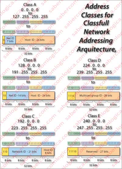
Thus, a new method came to light, where the addresses were represented by a so called Classfull Network Addressing Architecture, represented in Figure 1, a very lofty name meaning that the first 3 higher order bits of the address represent the class of address, existing 3 classes of unicast (addressed to one host): classes A, B and C.
So now we could represent more networks, leaving space for:
- Networks with many hosts (A), specifically 128 networks with 16,777,216 hosts each.
- A balanced number of networks and hosts (B), specifically 16,384 nets with 65,536 hosts each.
- Many networks with few hosts (C), specifically 2,097,152 networks with 256 addresses each.
Class D is reserved for multicast addresses and Class E is reserved for situations in future.
Subneting
But this method had limitations too, what forced the implementation of another method consisting in the division of a network into subnets.
Let’s look at the situation of an organization that has a network with 2,000 hosts. A Class C network doesn’t match because it only has 256 addresses. A Class B network, which has to be assigned to that organization has 65,536 addresses, thus wasting 63,036 addresses.
A method to subdivide network classes was them created, sharing the bits reserved for hosts in subnet bits and host bits. This method was called subneting, using for this purpose the network masks, which define the type of subdivision of networks, i.e. how many bits of networks space stay with networks and how many are for hosts.
In the case exemplified it’s enough to use the 3 low order bits of the low order byte dedicated to networks, we can represent 2048 hosts, which meet the needs of the organization. Thus, a subnet of class B represented by the mask 255.255.248.0 or in binary 11111111.11111111.11111000.00000000 is attributed to it.
The value of the sub-network is obtained by applying the AND operator to address and mask or the address bits matching the mask significant bits. The value of the host is obtained directly by the address bits matching the mask non significant bits, as shown in Figure 3, although this figure intends to illustrate another situation.
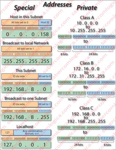
Special addresses with very specific meanings were created, as Figure 2 left represents. Were also defined private address spaces in the various classes, as the Figure 2 right represents.
The private address spaces are used for internal addressing of private networks as campuses, enterprises, etc., where, hiding behind a public address there is a LAN (Local Area Network), with only private addresses. To make this possible the gateway router of that LAN has to be NAT (Network Address Translation) able, meaning by this that it must be able to make the translation of private addresses to a public address. NAT will be specifically discussed below.
The addresses belonging to the private address spaces can not be used publicly, but they can be repeated in different LAN as each one has the meaning that each LAN gives it internally. Private addresses are attributed by the private LAN administrator, respecting the correct procedures.
But this process of dividing classes into sub-class networks (subneting), caused an exponential growth of routing tables. To solve this important weakness a new method arose, being now the current addressing method.
CIDR (Classless Inter-Domain Routing)
As it becomes from its name (Classless), classes were abolished by this method.
Now, each address has to be defined by its usual representation and another symbol “/”, followed by the number of bits dedicated to the definition of the network, i.e. something like a.b.c.d / x where x represents the number of bits in the adress which define the network, known as the network prefix.
Thus, if an organization has e.g. 15,000 hosts, an address a.b.c.0/18 is assigned to it, corresponding to 16,384 host addresses and in which only the highest order 2 bits of the 2nd order byte match network, referring the remaining 6 to hosts.
Good, but the computer doesn’t understand this “/”. How does it understand what is network and what is host. How does he know what to do when it receives the address 188.72.202.158?
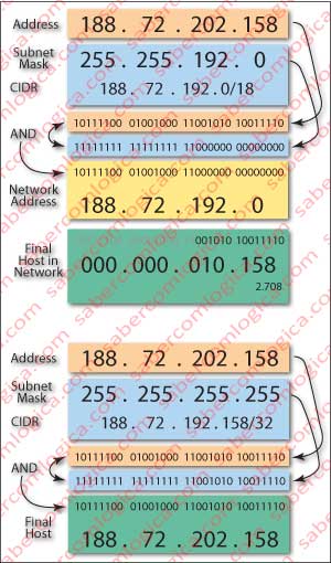
This is solved with network masks. The address above can have several meanings depending on the net mask that follows with it. Let’s look at Figure 3. To better understand this we must become computers and think in binary, not decimal.
Suppose that this address was followed by the mask 255.255.192.0 or 11111111 11111111 11000000 00000000 in binary. The mask is composed by a succession of 1 followed by a sequence of 0, as it results from the binary representation of its decimal value.
The network address can be obtained by applying the AND operator to address and mask. The part of the address matching the sequence of 1 from the mask 11111111 11111111 11 (the highest order 18 bits) represents the network. In this case the network address is represented by the binary 10111100 01001000 11000000 00000000 or in decimal 188.172.192.0.
The host address matches the value of the address bits coincident with the sequence of 0 in the mask 000000 00000000 (the lowest order 14 bits). The hosts address will be the binary 001010 10011110 or in decimal 0.0.10.158, i.e. the host 2,708 of that network, or the offset of the host in the network, since the network address refers to its base address.
An address followed by the mask 255 255 255 255 refers to a terminal address.
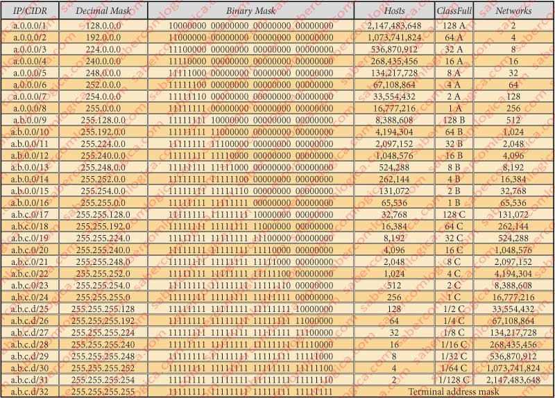
For informative reasons we leave an explanatory table of the possible CIDR addresses, with corresponding masks in decimal and binary, with corresponding ratings in ClassFull, quantities of hosts and networks, represented by Figure 4.
One of the most important changes CIDR introduced was the drastic reduction of routing tables size (soon we will see what this is). This way a router can present itself to the world in a easiest and reduced manner.
It simply says: all addresses whose first 18 bits match this one are my responsibility.
A Case Study – NetByCabo
This case is represented in Figure 5. To a certain hypothetical ISP (Internet Service Provider), NetByCabo (any resemblance with reality is purely coincidental) pretending 15,000 addresses, is assigned one address represented by an IP/CIDR 182.72.192.0/18 therefore 255.255.192.0 being the mask, which, according to the table in Figure 4, represent 16,384 addresses.
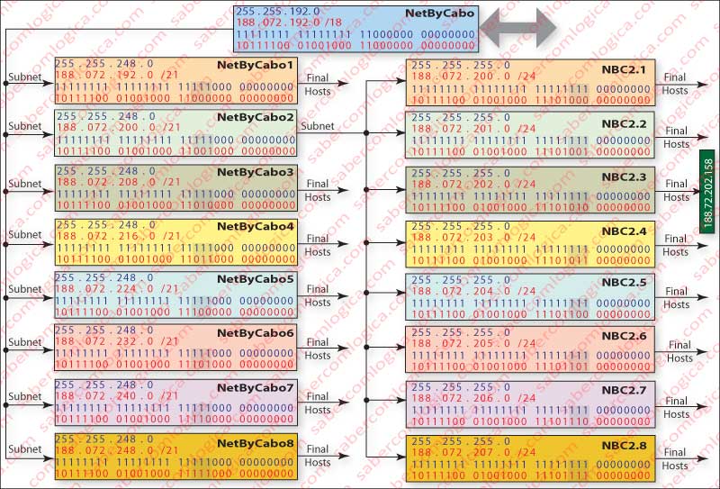
The way NetByCabo presents itself to Internet is with the address 182.72.192.0/18, which means: “All addresses beginning with the same first 18 bits must be addressed to me, being their subsequent routing of my responsibility”.
But NetByCabo has 8 subsidiaries that manage all its addresses and wishes that they will be sliced by them. Then assigns an IP/CIDR address to each adding 3 bits to its mask to create their mask, i.e. the mask 255.255.248.0.
The network addresses resulting from the possible combinations of the 3 added bits are 182.72.(192, 200, 208, 216, 232, 240 and 248).0/21 which become the addresses of each new network with 2048 hosts, organizations NetByCabo 1 to NetByCabo 8.
Each of these organizations shall be responsible for routing its 2,048 addresses. NetByCabo 2, acting in a region of greater users dispersion, also decided to divide its addresses by 8 other its own subsidiaries. So likewise does the division of its addresses, adding them plus 3 bits, resulting from the 3 added bits possible combinations 182.72. (200, 201, 202, 203, 204, 205, 206 and 207).0/24, corresponding to the IP/CIDR adress of each new network with 256 hosts each, to give to organizations NBC 2.1 to NBC 2.8, which will manage their routing, getting the mask 255.255.255.0
Finally, we seek the host address 182.72.202.158, which will be provided by organization NBC 2.3, announcing the fact with its IP/CIDR network address 182.72.202.0/24.
In order to better understand IP/CIDR addressing, it’s important always reasoning in binary, not decimal. Actually that’s the way the computer will understand it. Decimal CIDR address exists for us to understand each other.
The significant bits of the mask match the address bits that define the network. The non-significant bits match the address bits that define the host.
Broadcast
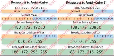
A Broadcast transmission sends a message to all hosts on a network or subnetwork. By definition, the IPv4 address of a broadcast to a network is obtained:
- Setting all unset bits of the mask (which define the host), thereby obtaining the offset value for that address regarding the network’s base address.
- The mask defines network’s base address.
- The broadcast address of a network will result from the sum of the two previous ones.
Figure 6 illustrates how to obtain broadcast addresses to network NetByCabo and subnetwork of NetByCabo 3, following the method described.
The Broadcast address 255.255.255.255 (all bits to 1) is by definition the broadcast address to the LAN, i.e., the address a network host uses when it wants to send a message to all hosts on its network. The gateway routers of any network don’t let this address go to the outside of their LAN.
Unicast is sending a message to a exclusive host.