
Multiplication
The iteration method used for the division is the same which must be used for the multiplication. From its application will result a circuit whose conception will use a similar reasoning to the one used for the division. Anyway we will not do it now.
The objectives of exercising a logical reasoning using known logic circuits in order to get the logical solution for a more complex situation and understanding the signals’s propagation along the Clock Cycle are met.
As a challenge to the development of logical reasoning and to test your knowledge about signals’s propagation along the try to develop a multiplying circuit for two 4 bit numbers in 2’s complement using this method. We’ll be here to help.
Comparison
Five is bigger than three.
Ten is smaller than twenty.
The set of people living in Tokyo is bigger than the set of people living in Lisbon.
The Lead specific weight is bigger than the Cotton specific weight.
The value of the derivative of f(x) when x=2 is bigger than when x=3.
These are examples of comparisons between absolute values or between values resulting from the calculation of mathematical expressions, but always between entities of quantifiable greatness. The comparison between two values is a frequent operation realized by any computer program in conditional instructions, in most languages represented by
If (x) Do This Else Do That
being the declaration contained in If the path to follow if the expression (x) is true and the declaration contained in Else the path to follow if (x) is false.
Observation:
In mathematical logics the expression contained in (x) is called Predicate, so giving birth to Predicate Calculus. What we evaluate within the expression (x) are human quantified values. The result of that evaluation will always return only one of the duality true/false values.
The most common standard mathematical symbols expressing the comparison between two values are:
- > (greater than),
- < (less than),
- = (equal to),
- ≠ (not equal to),
- ≥ (greater than or equal to) and
- ≤ (less than or equal to).
What we intend to do with this circuit is to compare two values, namely two numbers in 2’s complement. What for us humans is not difficult.
But how do you do that on the computer?
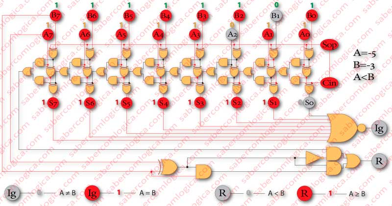
We’ll proceed as usual with a logical reasoning as the way to get to a conclusion, with the help of Figure 1, where two 8 bit 2’s complement numbers A (A0 to A7) and B (B0 to B7), A7 and B7 representing the respective signs, are compared.
First we examine the signs of the numbers to be compared. If they are different, the greater is the one with the positive sign. If they are equal, we’ll have to analyze their subtraction.
So, for now we’ll have to distinguish if their signs are different or equal.
At this point, the way to do this should already be clear to anyone who is reading this work. It’s through the XOR operator, which returns 1 when both operands are different, and 0 when both they are equal.
So, let’s connect both A7 and B7 to a XOR gate and do our analysis separated to both situations.
WHEN THE SIGNS ARE DIFFERENT
In this situation XOR returns 1 and the biggest number is the one with a positive sign, i.e. the one whose highest order bit is 0.
Now we must know which is the positive and which is the negative. As the sign of both them is different then we’ll only have to discover the sign of one of them. Let’s choose B.
To know if B is positive or negative we’ll compare B7 with XOR output, which we know to be 1. To do it, an AND operator fulfills perfectly this task, returning 1 only when both the operands are 1.
So let’s connect XOR and B7 to an AND gate.
- If AND returns 1 it’s because its inputs are both 1. Thus, B7 is 1, B is negative and A>B.
- If AND returns 0 it’s because its inputs aren’t both 1. Thus, B7 is 0 ,B is positive and A
Thus, when A and B have different signs it will be B sign (B7) which will define the relation between A and B. If B is negative A>B and if B is positive A
WHEN THE SIGNS ARE EQUAL
When we began with this Chapter we talked about the question of the carry out value in a subtraction of two positive numbers, using the table in Figure 1.
We can noticed tha there exists a relation between the carry out of a binary numbers sum and the signs and values of its operands. Let’s check what that relation is and its applicability in this case.
If A and B are both positive, the current situation is identical to the one described there, i.e. the sum of A (positive) with B symmetrical (negative) will be done, reason why we can conclude that: If the carry out is 1 then, in absolute value, A≥B.
We are not comparing absolute but real values, correct?
Starting with the absolute values we can get to the real ones. Since A and B are positive, their real values are equal to their real values, reason why we can conclude that:
When A and B are both positive if the carry out is 1 then, in real value, A≥B.
If A and B are both negative we only have to invert the place of the sum operands (addition commutative property) in order that the addition to be executed is of B (positive) with A symmetrical (negative). With B occupying A place and A occupying B place in the table of Figure 1 the same way and using the same reasoning as for the previous situation, we can conclude that: If the carry out is 1 then, in absolute value, B≥A.
Since A and B are both negative their actual values are equal to the negatives of their absolute values. And the greater a negative number’s absolute value is, the smaller the number actually is, as for instance 5>3 but -5<-3. Generalizing, if B≥A in absolute value, in real value B≤A or A≥B. So we can conclude that:
When A and B are both negative if the carry out is 1 then, in real value, A≥B.
We have found the relation between the carry out of an operation and its operands size, when they are both negative, which is:
When A and B have equal signs, whatever their sign is, when the Carry Out is 1 then A≥B and when it is 0 then A
AND NOW FOR EQUAL OR DIFFERENT SIGNS
We have two answers for the same problem. One when both A and B have the same signs and another when they have different signs.
And now, how does the circuit know which one to choose?
Well, to select between two inputs we can use a 2-to-1 MUX. But we must find a selection bit for it to select between one input when A and B signs are equal or another when A and B signs are different.
It seems that the output value of the XOR gate which analyses the signs of A and B will do it perfectly.
- If XOR returns 0 its because their signs are equal. It will select the input E0 where we will connect the adder carry out.
- If XOR returns 1 its because their signs are different. It will select the input E1 where we will connect the AND gate output, its value being (A7 XOR B7) AND B7.
Now we can say that for any values of A and B, the MUX’s output will be 1 when A≥B and 0 when A
So, how does the circuit will now be informed about which of the two situations is occurring?
Let’s see. If A and B are equal, the result will be 0 for all the bits and the Carry Out will be 1. Right?
Therefore, we just have to connect all the result’s bits to a NOR gate that will only return 1 when all inputs are 0, thus when A and B are equal.
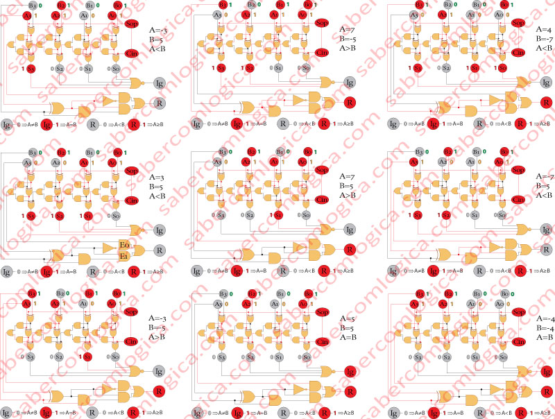
We place here together in Figure 2 the analysis of several different situations where some possible relations between A and B signals and values were tested.
Conclusion
This circuit gives us an answer with two bits,thus with two difference informations.
If we call R to the MUX output, then
R=1 → A≥B
R=0 → A
If we call Ig to the NOR gate output,then
Ig=1 → A=B
Ig=0 → A≠B
And this way we will know if A is bigger, equal or smaller than B.