
Network Layer
Finally we reached the kingdom of Mr IP (Internet Protocol).
IP is the network layer protocol on Internet and has no competitor. It’s IP the responsible for providing the packets with the necessary information for them to find its destination. And this is not an easy task. This is the layer upon which more has been researched and written.
When a packet travels from a sender to a recipient doesn’t follow a straight path. It is not like the Express, being more like the mail train that stops at all stations.
Remember the cars carrying the leaves of our message?
IP puts destination and sender addresses on the packets that carry the leaves of our letter, delivers them to the little cars and sends them in the path to the recipient. Along the way they will find many intersections (train stations) and roads with different sizes and speeds. When they reach an intersection they need to know which road to follow. Therefore, at every intersection is a signalman, that we call Router. The roads between our computer and the first signalman, between the several signalmen along the path and between the last signalman and the recipient, are called links.
In the analysis we made of the application layer and the HTTP protocol, a DNS query was performed to get the address by the name of a server to which we wanted to request a web page. It was condominiopartners.pt and DNS returned the address 188.72.202.158, that wasn’t useful for us untill now. It was reserved to be used in this layer by Mr IP.
Now, Mr IP picks that address and puts it in the destination address of the packets that take the leaves of our letter.
Now imagine the poor drivers of the cars, having to deliver the packets only with this kind of addresses.
It’s easy for us to go to any place since we are given the correct address (continent, country, city, street, door number and floor). Having a map, something we invented, and which represents all points of the earth related to each other, it shows us where we are and how the place we want to go is related to it. But drivers do not have a map for this type of addresses. These addresses don’t even correlate places with their code. They will need to start asking their way from its starting point and keep asking it along the path to the signalmen they will find, rising and then descending the hierarchy (village, city, country, continent, country, city, village) until they reach the destination.
It is Mr. IP that will help drivers in this task, teaching the signalmen which addresses lead their neighbors to (routing), so they can guide drivers. The signalmen will direct the drivers to its destination according to the routes they know.
Let’s see how.
IP protocol is based on Best Effort service model. IP doesn’t ensure bandwidth, reliability, order delivery or even delivery. IP simply makes the best effort to drive packets to its destiny.
IP engages core concepts on the Internet, such as Addressing, Routing and Forwarding.
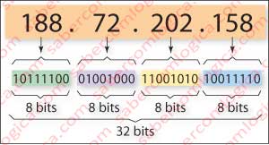
- Addressing corresponds to assigning a number as the one in Figure 1, unique to each machine in a given moment.
- Routing, determines the best route to go from departure point to arrival point.
- Forwarding deals with directing each packet in the routers through which they will go through, i.e. direct them from their input to their proper output.
An IPv4 address, as shown in Figure 1, consists of 32 bits divided into sets of 8 bits separated by dots. Its representation for us is in decimal format. How it works is an issue we shall soon see.
IP Header
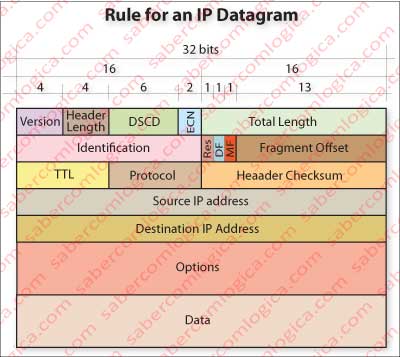
Let’s move on to the analysis of the fields of an IP header, as shown in Figure 2. Once this header is put together with the Segment, the new packet assumes the designation of Datagram.
Version – The first 4 bits describe the IP version used in the datagram. Here we are going to analyze is version 4 (IPv4), the one used so far on all computers connected to the Internet, although it is in a slow process of replacement by version 6 (IPv6), because IPv4 available range of addresses is almost exhausted .
Header Length – The second 4 bits of the header refer the number of words of 32 bits that compose the header. Normally they shall be 5, if the options field is empty, what matches 20 bytes. The maximum number represented by 4 bits is 15. So, the header can never be more than 60 bytes long, and its size will always be a multiple of 32 bits or 4 bytes.
DSCP (Differentiated Services Code Point) or Type of Service – This field is important for IP to know the type of service the datagram is intended to, so they can have different ways of being processed according to their type.
For example if a datagram belongs to a real time application such as Voice over IP (VoIP), Video and/or Audio online over SCTP (Stream Control Transmission Protocol) or UDP its processing will be different from a datagram that belongs to a non-real-time application like Web, e-mail, a file transfer over TCP or a video and/or audio file. Real Time applications are those who execute while they are receiving the file, such as Radio program, a TV program, a video online – e.g. You Tube, etc.).
ECN (Explicit Congestion Notification) – These 2 bits are used by ECN which runs over IP. As mentioned above, it is through these two bits that the network layer informs the recipient terminal equipment on the situation of congestion (CE=11), falling on the TCP layer acknowledgment which in turn will use TCP flag ECE set in its segment in order to inform the sender.
Total length – the total length of the datagram, including header, is indicated by this field of 16 bits. The maximum value is 65,535 Bytes which can be displayed and the minimum value that any host is forced to ensure is 576 Bytes. Currently most Hosts already support much larger packets, but there can always exist network links that the datagram will traverse, that don’t support such values. In order to solve it there’s the possibility of datagram fragmentation and reconstruction, using some fields in the header. We’ll soon go there.
ID – This field is used to unequivocally identify the fragments of a datagram, in case of fragmentation.
Flags – This 3 bit field is used to control fragmentation of datagrams, when that’s the case:
- Bit 0 – reserved. Must be 0.
- Bit 1 – (DF) datagrams can not be fragmented. If DF is set and datagram needs fragmentation, it is dropped and is sent to the sender an ICMP (latter we’ll see what this is)message describing the event.
- Bit 2 – (MF) This bit indicates whether there are or not more fragments. If MF is unset it’s because the datagram is not fragmented. If MF is set, it means that there are more fragments of the same datagram, until it returns to unset, what implies that there are no more fragments of the datagram beyond this one. In this situation the Fragment Offset field must be nonzero, being the reason why the host distinguishes this situation from the one which indicates that a package is not fragmented.
Fragment Offset – This 13 bit field represents the value, measured in units of blocks of 8 Bytes, from the beginning of the fragment in question. Part of the value zero for the first fragment and represents up to 65,528 Bytes ((213-1) x 8), which exceeds the maximum length of 65,535 Bytes.
TTL (Time To Live) – it’s an 8 bit field which registers the maximum number of routers the datagram can go through. For each crossed router TTL is decremented. When it reaches zero, the packet is discarded. The idea is to prevent a pack to walk forever lost on the net, in endless loops. When it is discarded, an ICMP message is sent to the sender describing the event.
Protocol – This code defines the protocol used in the data portion of transport (the segment), i.e. the protocol of the layer above this.
Checksum – for this field are intended 16 bit. The operation has already been described above, in the transport layer. In this layer, checksum is intended to verify the data integrity of the header. In each router is verified if there has been any change. If so the datagram is discarded. Each time the datagram goes through a router, TTL is decremented. Thus, the value of checksum must be computed again so it can be confident in the new reading.
Source address – This field contains the IPv4 address of the sender, 32 bits long.
Destination address – This field contains the IPv4 address of the recipient, 32 bits long.
Options – the datagram may contain options in this field, which must always be a multiple of 32 bits, using a padding (fill in the missing bits with zero) for this purpose if necessary.
Once completed the header, the datagram is ready to be sent to the link layer, to continue its path.
Whoever wants can follow it, but I strongly recommend remaining here to realize how the IP protocol solves the main tasks devolving.
During the datagram header description we mentioned Fragmentation and ICMP messages also. Two more issues that we will analyze just now.
ICMP (Internet Control Message Protocol)
ICMP is used by terminal equipments and routers to exchange messages between themselves.
Because routers do not rise to the level of transport protocol, this type of messages at network level, allow the routers to exchange messages with terminal equipment.
ICMP messages are very small, essentially about errors and defined by codes and types. It may seem that this protocol operates at the network level, but it isn’t quite like that. For all intents and purposes an ICMP message is sent over IP and IP header signals that the upper level protocol is ICMP. An ICMP message uses the IP header by filling out the fields according to the case, i.e. the Protocol is ICMP code, the target is the source of the datagram to whom if wishes to convey the error and the source is the router that sends the message.
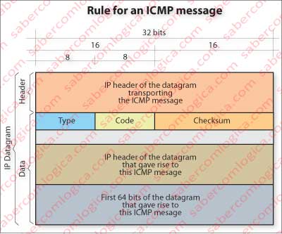
Let’s follow the description with Figure 3.
The message itself will be in the IP message data field. The first Byte contains the type, the second Byte contains the code and the two following Bytes contain the Checksum for the message. The second block of 32 bits is empty and available for service issues.
In the remaining blocks of 32 bits are the IP header of the original message and the first 64 bits of its data field.
Why the first 64 bits?
The header allows the sender to identify the datagram and the first 64 bits of the data field, which match the first 64 bits of the segment containing the start of the TCP header with information about the segment’s sequence number and the terminal sender port, allow the sender, if it is a terminal, to reach upper layers when needed.
For example:
- Type 11 with code 0 indicates to the sender that the message was lost because its TTL has expired.
- Type 3 with code 4, warns the sender that a datagram was dropped because it needed to be fragmented, but as DF was set that couldn’t be done.
- Type 3, combined with different codes, indicates the impossibility of proceeding with the datagram because the network, the host, the port or Protocol are unknown or unable to reach.
But ICMP is used for purposes other than error messages. It’s through ICMP that the Operating Systems perform the PING and TRACERT commands.
When a host wishes to verify the network and the connection with another host, it sends a PING to the address of that host. The Operating System sends an ICMP message type 8 and code 0, which asks an echo to that host -this is PING. This host in turn sends in response another ICMP message type 0 and code 0 which is an echo reply to PING (let’s say it’s a Pong).
When a host wishes to know the routers that a packet crossed to the target, and the RTT to each of those routers, OS runs the TRACERT command. This command sends a sequence of ICMP messages with TTL started at 1 and incremented for each message that follows. The result of this procedure is that the TTL will run out in the first, second, third, …, nth router and finally at destination. ICMP return messages for each of the sent packets give indications about the routers that sent them, and timings that they have on sender give indication of RTT for each packet upon arrival.
If you feel comfortable working with command prompt, try entering, for example commands:
ping www.google.com
tracert www.google.com
and see the result you get.
Datagram Fragmentation
A packet goes through a series of links from its origin to its destination (e.g. Lisbon to Sydney). It will find advanced links, ancient links, cable links, fiber optic links, satellite links, radio wave links, microwave links, etc.
Link is the set sender, physical connection, receiver of each path section. The differences between links will be sensed, e.g. when the size initially assigned to packets (MTU) is not compatible with the maximum size allowed by a specific link (MTU).
Drop the packet and send an ICMP message to the sender should be the easiest solution. But, precisely to prevent this, was created at network layer the possibility of fragmenting datagrams.
Why doing it at this layer’s level if it is already done at TCP level?
Because it is intended to be done by the routers which only open the packet to the network layer. Thus, when we want a router to pass a packet from an incoming interface to an outgoing interface whose MTU is smaller than its size, it has to be fragmented.
To do this the router will use the original datagram IP header fields designated to situations of fragmentation and build datagrams that fall in the maximum dimensions allowed by the outgoing interface. How to fill and use the fields for this purpose is described in the area where we made the analysis of IP header fields.
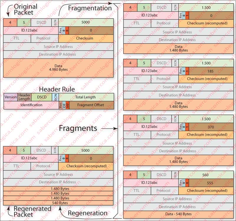
Once the fragments arrive at the destination, the original datagram must be reconstructed . That is made by the recipient who does it by putting together all fragments with the same ID and the MF flag set, plus the firs fragment with MF flag unset and with the offset field filled, which is the last fragment. Then the recipient removes fragments headers, assembles fragments in the appropriate order, and adds the header of the original datagram. Figure 4 attempts to illustrate what we just described. The evolution of total length values, MF flag and fragment offset can there be checked.
Fragment’s offset always indicates the first byte of each datagram on a scale of 8 bytes, referring only to the data payload. Thus 0, 185 (1480/8), 370 (2960/8) and 555 (4440/8) are the positions of first byte (offset) of each of the fragments.
The original datagram is regenerated only at the final host. It’s intended to avoid further complications in routers protocol and more work for them.
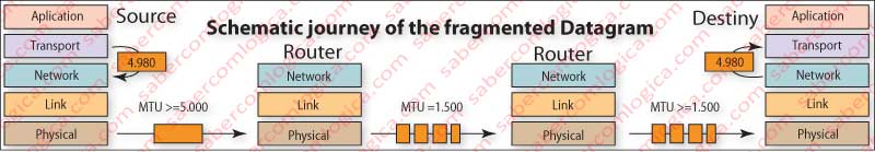
To help the comprehension of fragmentation process, another graphic with the layout of a fragmented packet’s trip was placed in Figure 5.