
NTFS – Generalities and Getting In
Before we go into the details of the file system, we are going to establish the way we are going to organize this analysis.
The NTFS has a very complex description which can easily become confuse. It’s frequent that for the understanding of some steps we need to understand first the step which explains them, but the understanding of this one depends from the others. And this is the risk we’ll try to avoid.
First of all we are going to define a concrete purpose through which we are going to evolve as the way to understand the NTFS.
The purpose:
Finding in the HDD, using a hexadecimal editor, the file whose path is:
G:\Todas as Imagens\Diversos Pessoais\Diversos 1\Diversos 1999\Picture4.jpg
All the NTFS actions which have no direct connection with this purpose won’t be analyzed. To someone we’ll make a generic description of its operating mode, but never getting into details.
Even this way the description will be long enough. f we wouldn’t do like that, our book wouldn’t be enough to describe it.
Now let’s see in a resumed fashion the method we used to this job, thus the method which must be followed by who reads it in order to understand it.
The File is the center of any file system. In NTFS a File is defined by a header or descriptor e by a set of attributes.
For this reason, before doing the analysis of any File we are going to understand how we can read a file descriptor and how we can read the attributes which matter for the analysis of the files we need.
Once finished this part we’ll have the conditions to read the files definition.
We can distinguish two types of files in NTFS. Our files, those we use and for which the system was created and the metadata files which contain all the information needed to reach the first ones.
We’ll start our analysis by the metadata files which will allow us to get to the bottom line and teach us how to proceed.
Only after that we’ll start our journey from the bottom line until our purpose.
All the information about our files is concentrated in a master table, the MFT (Master File Table), whose organization will be described by a metadata file. To find the files we’ll have to go through a tree of indexes, described by files of type Index that we’ll be teach to work with by metadata files too.
In our journey we’ll frequently have to get backwards in order to, through the reading of an already analyzed table be able to understand the content of a file.
Let’s proceed.
PBS (Partition Boot Sector)
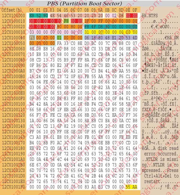
After this short navigation, here we are at the offset 12C0100000h. As we were hopping we found there the 2nd partition boot sector, represented by the hexadecimal editor as we can see in figure 4.
From now on the partition is dealt as if a real HDD it were, a Volume, and the boot sector of that Volume is its 1st sector, thus in the offset 0000h. All, the offset references will be relative to the partition zero.
The 3 bytes from offset 0000hm to 0002h are a jump instruction.
The 8 bytes from offset 0003h to 0009h are the OEM ID (Original Equipment Manufacturer IDentification), which identify the name and the version of the OS which formatted the volume.
The 25 bytes from offset 000Bh to 0023h (lowest shadowing) are the BPB (Bios Parameter Block), which we’ll just describe in detail.
The 48 bytes from offset 0024h to 0053h (lowest shadowing) are the BPB extension.
The 426 Bytes from offset 0054h to 01FD care the boot code which in the active partitions will load the SO into memory and launch it, thus delivering to it the control of the operations from now on.
The last 2 bytes are the boot sector signature.
BPB (Bios Parameter Block)
In Figure 4a we detach the BPB from the PBS having its different fields color shadowed regarding a better analysis.
The 2 bytes 000Bh and 000Ch identify the number of bytes per sector. In our case they will be 02 00 = 512 B, which is the standard value.
The byte in 000Dh designates the number of sectors per cluster.
In our case there are 8 clusters. so, each cluster has 4 Kb, which is usually the value set by NTFS.
The bytes from 000Eh to 0014h, from 0016h to 0017h and from 0020h to 0023h, must be always kept at zero, as the fields that they define, not being zero, cause a failure in the NTFS when mounting the Volume.
The byte 0015hThe defines the type of device wherein the partition is installed.
The value F8 of our case defines the HDD.
The bytes from 0018h to 001Fh, from 0024h to 0027h, from 0041h to 0043h, from 0045h to 0047h and from 0050h to 0053h aren’t used by NTFS, reason why it doesn’t matter whatever is written in them.
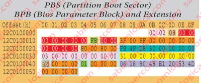
The 8 bytes from 0028h to 002Fh designate the number of sectors in the volume. In our case they will be 30D84FF8h or 819,482,616 sectors.
The 8 bytes from 0030h to 0037h designate the LCN (Logical Cluster Number) where the $MFT file starts. In our case it begins in the cluster 3, i.e. its offset is of 24 sectors (3000h), relative to the beginning of the partition.
The 8 bytes from 0038h to 003Fh designate the LCN where the $MFT MIRR file starts. In our case it starts in the cluster 31h, or 49 in decimal, thus existing 392 sectors before it, having the offset 31000h relative to the beginning of the partition.
The byte in 0040h designates the size of each MFT register.
- If this value, when read in two’s complement, is positive, i.e. if its value goes from 00h to 7Fh (0000 0000 a 0111 1111), it actually designates the number of clusters per register.
- If this value, when read in two’s complement, is negative, i.e. if its value goes from 80h to FFh (1000 0000 a 1111 1111), the size in bytes of each register will be equal to 2 to the power of the byte absolute value.
In our case its value is F6, which converted in binary is equal to 1111 0110, a negative value. Its absolute value or its symmetrical is 00001001+1= 00001010, what in decimal is equal to 10. As 2 to the power of 10 (210)=1024 bytes or 1 KB, that is the size designated for each MFT register.
The byte in 0044h represents the number of clusters per Index Buffer. As in the previous case,
- if positive (00h to 7Fh) it designates its size in clusters,
- if it’s negative (80h to FFh) its size in bytes is designated by 2 to the power of the byte absolute value.
In our case its positive and its value is 1. So the size of each Index buffer is of 1 cluster.
The 8 bytes from 0048h to 004Fh designate the serial number of the volume.
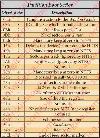
Figure 5 represents a table with the synthesis of all the information provided by the PBS analyzed until now.
MFT ( Master File Table)
We have used for several times the name of MFT (Master File Table), which is the table where the NTFS keeps a register or entry for each existing file.
First let’s understand the difference between the two types of files existing inside the MFT:
Normal Files, which are those containing the information about our data.
Metadata Files, which are those containing information about the Volume and the Normal Files. The name of these files always begins with $.
All the entries in the MFT are files. Whether they refer to Normal Files, to Metadata Files($) or to Index Buffers (Folders).
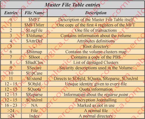
The first entries in the MFT are, as we can see in figure 6, Metadata files
Until the entry 11 we have the metadata files ($), those who teach us or the system to work with the file system. Above the entry 24 are the entries for the Files and Indexes themselves.
In the description of these files the NTFS complexity becomes very dense. We’ll have Metadata files pointing to themselves, as is the case of the $MFT file.
A little interruption to introduce some important concepts which will be called during the following descriptions.
Update Sequence and Update Sequence Number
One File is contained in at least 2 sectors or 1KB (a file can be contained in its own entry in the MFT if it fits there) and an Index File in at least 8 sectors (1 Cluster). But both them can occupy more sectors if they have extensions.
Due to the possibility of a file dispersion through multiple sectors, the NTFS sets in the last 2 bytes of each sector containing the same file the Update sequence number defined for it in a process called FIXUP. This way, the system can obtain the confirmation that a given sector actually belongs to the sequence of sectors of a given file.
But this way we’ll lose the information which was in those 2 last bytes?
No, because NTFS keeps in the update sequence, by order, the bytes replaced in all the modified sectors. The update sequence will have as many words (2 bytes or 16 bits) as many the file descriptor sectors plus one, the first, which is precisely the update sequence number. That’s where the NTFS will look for the necessary information when reading the replaced bytes.
Each time the file is updated the update sequence number is incremented, so that it won’t ever point to out of use files (old extensions).
It’s maybe easier to understand this if we think in what happens after a disk defragmentation. The descriptor of a big file spread along the disk can occupy several sectors. But after defrag its descriptor will probably fit into the base sector.
So being, in ex-extension sector the byte defining its use is changed and in the base file the update sequence number, is incremented. This way the now unoccupied sector is no longer pointed by this file.
Hard Link
This is the designation of all the links or pathnames which point to a file.
Windows 7 and newer versions users can better understand one of the uses of this if we tell them that the Explorer folders which they cannot access (they have an arrow on them) refer to folders or paths used in older versions. For instance in C:\Users\User the folder called Application Data is now called AppData. If the older folder wouldn’t exist the older programs referring to that path wouldn’t work anymore.
These Hard Links point to the new and correct path, have no content and only the system can access them and provide the compatibility with older versions. They are not folders but links to a file.
Reparse Point
A reparse point is a little piece of code into a file including a reference to a file system filter which shall be used to read the file.
When the reparse point is detected during the file reading the system calls the designated filter to fulfill its predefined function.
Let’s try to see it in a practical way. Think in the desktop Icons where we click to open a program. We call them shortcuts, or quick path for a given program executable or file. Remember that inside the HDD everything is a file. And the such Icon is exactly a little file with a reparse point which, when detected, calls a file system filter which reads and executes it, opening the intended file which is pointed through it.
The same way, the folders we have already referred in Windows 7 and upper versions which ensure the compatibility with the older ones, contain a reparse point which, in a transparent way for the user, redirect what is sent to them to the address they are pointing at.
Sparse File
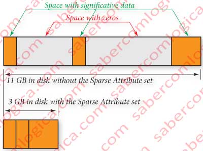
A Sparse File is a file containing great spaces filled with zeros inserted between little spaces with significate data.
In order to spare disk space, only the significate spaces are kept in disk and the system keeps a reference to the spaces with zeros, their size, localization and quantity. See figure 12-17.
When the file is read, the part kept into the disk is filled with the read data and the part not kept in disk, which the file system knows, is filled with zeros.
There aren’t many file systems supporting this functionality. The NTFS is one that does support it.
The sparse files can easily become fragmented. Whenever a copy of the sparse file is made to work in another file system which doesn’t support this functionality the file is reconstructed and kept with its full size.
Namespace
The Namespace of a file designates the space of name definition where it belongs. Those spaces are as follows:
- POSIX – 255 characters and Unicode, case sensitive.
- Win32 – 255 characters and Unicode (the difference is in the limit of accepted characters)
- DOS – 8 uppercase characters followed by a dot and 3 more characters.
- Win32 e DOS – Means the name was written in a way that can be inserted into the 2 spaces.
The NTFS, for compatibility reasons, describes the files inserted in the namespace 2, repeatedly with the namespace 3, i.e. the files having a name with more than 8 characters are described in the namespace 3 and converted to 8 characters in order to be described in the namespace 2 too.
In our case the file name has 8 characters, therefore being described only in the namespace 3, representing the DOS description. The names in DOS can have up to 8 characters plus 3 characters for the extension.
Our name has 8 characters and no extension. We mustn’t forget that the name of the file we are analyzing is $AttrDef. We have already mentioned a lot of other names but we were referring the names of attributes of this file. The exposition is going large but the file is still the same.
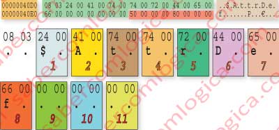
The way as the name is described can be seen in figure 12-18. In the top of that figure we can see the hexadecimal editor representation of that part, with the text that the editor presents at the right. At the lower part of the figure we represent character by character the 11 characters allowed by the DOS.
Why do they all have a dot after each one?
The name characters are represented in Unicode. The Unicode uses 16 bits to represent all the possible characters of all the written languages in the world, added with all the special characters.
The lowest order byte (don’t forget that they are in inverted order) correspond to the extended ASCII (ANSI), which is represented with 8 bits.
The highest order byte is a complement to the previous in order to create the Unicode. But in the text editor the bytes are read one by one by the ANSI code (extended ASCII) and 00 is read like a dot.
In Unicode, the set of the 2 bytes is read with the same value as ANSI reads the lowest order byte.
And the 3 characters for the extension?
This file, as we can see by its name, has no extension. The extension is used for files like .txt, .jpg, .doc, etc.
A curiosity: The extension doesn’t compromise the file content or operation. It’s only an indicator for the OS to know the program that it shall use to read that file. If we put a .jpg extension after a word document, what happens if we try to open it is that the OS will try to do it with an image editor program and will fail. But if we open the Word program and then choose to open the file, it will open correctly.
OK! We’ve introduced enough concepts. Let’s proceed with the File analysis starting by its descriptor and then going to its atributtes.
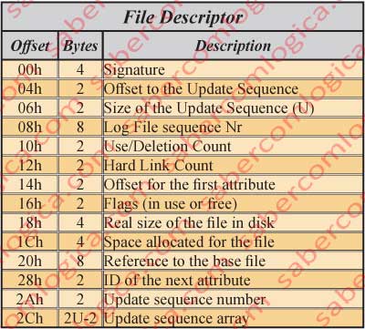
File Descriptor
The descriptor of a file must be read according to the table in figure 7 which we are going to analyze in detail. We’ll use the hexadecimal editor image of the $AttrDef file which we’ll use further on, shown in figure 32.
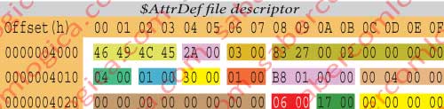
The $AttrDef file descriptor, shadowed in yellow, is described with detail in figure 8 decomposed in its several fields, which we are going to use for a comparison between our case study and the descriptor table of Figure 7.
The 4 bytes from 4000h to 4003h designate the Signature. In our case is FILE.
The 2 bytes in 4004h and 4005h designate the Offset to the Update sequence. In our case 2Ah.
The 2 bytes in 4006h and 4007h designate the size of the update sequence in words. In our case 03h (3 words or 6 Bytes).
The 8 bytes from 4008h to 400Fh designate the Log File sequence number – 02002783h in our case. This number changes each time the register is changed.
The 2 bytes in 4010h and 4011h designate the use/deletion count – 04h in pour case. This represents the number of times that this register space was reused. It’s incremented for each time the register it contains is deleted.
The 2 bytes in 4012h and 4013h designate the Hard Link count – 01 in our case. It represents the number of directory entries referring to this file.
The 2 bytes in 4014h and 4015h designate the offset for the first attribute, 30h in our case. It’s where starts this file 1st attribute description. This offset can change according with the update sequence size, which we already verified that has different sizes according to the number of sectors occupied by the file.
The 2 bytes in 4016h and 4017h are the Flags – 01 in our case, which means that this register space is in use.
- 00 – Register space free
- 01 – Register space in use
- 02 – The register is a directory
The 4 bytes from 4018h to 401Bh designate the real file size – in our case 416 Bytes. It represents the number of bytes really used by the file added with a padding to the nearest multiple of 8 bytes. Here the padding aligns the information to 8 bytes, half line of the hexadecimal representation.
The 4 bytes from 401Ch to 401Fh designate the allocated size for the file, which in our case is 1024 Bytes. It represents the space each file occupies in the MFT, which is 1 KB (2 sectors) or a multiple of that if it has extensions.
The 8 bytes from 4020h to 4027h refer the base register– 0 in our case. When it’s zero we are dealing with the file base register in the MFT. If it’s different is because we are dealing with an extension of the base register and, so being, it points to it.
The 2 bytes in 4028h and 4029h – Next attribute Id – 6 in our case, what means that the next attribute getting into this file will have the ID=6.
The 2 bytes in 402Ah and 402Bh designate the Update sequence number. This is the first of the update sequence words.
The 4 bytes from 402Ch to 402Fh designate the remaining words of the update sequence. They contain the value of each of the last 2 bytes of the file or extensions replaced by the update sequence number.
Because this question of the Update Sequence and Update Sequence Number can still be confuse we’ll profit from this real case to try to turn it clear. As we’ve seen our file occupies 2 sectors (1KB). So being the Update Sequence is defined by 3 words:
- The first one designates the Update Sequence Number, the one which will be at the end of the file sectors, which is 17 00.
- The next 2 words designate the value which was in the last word of each of the 2 sectors, replaced there by the Update Sequence Number. Their value is 00 00 and 00 00.
We are now going to start the analysis of the File Attributes, in the next article.