NTFS – Attributes (continuation)
Non Resident and No Named Attributes
Non-Resident and No Named Attribute Header Type
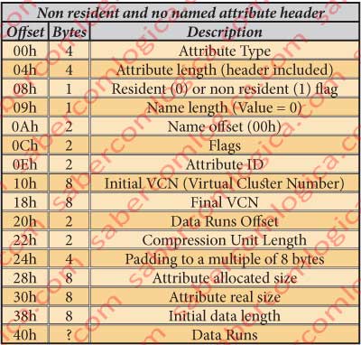
We recall that in the end of the previous article we were going to describe the $DATA attribute but we left it to this article as it is a non resident and no named attribute, thus with a different header. This header structure for this attribute. So being, we are going to add here a table in figure 20 with this header type fields description. And we are just going into the $DATA attribute .
$DATA Attribute

As a non-resident attribute, its composition inside this file content is limited to its header, as the data is somewhere outside this file in MFT. Sso being we are going to describe this attribute body within this attribute analysis. We start by the fields which match with those of the previous type. This $DATA attribute is represented brown shadowed in the figure 32. In figure 21 we have the hexadecimal editor detailed representation of the $AttrDef file $DATA attribute header, decomposed in its different fields, each shadowed in a different color.We can read that:
It’s an attribute with the type 80h, i.e. it’s a $DATA attribute.
The attribute length is 48h, thus the next attribute beginning at the offset 4068h + 48h = 41B0h.
It’a a non resident attribute, what means that its data is not here, inside this file but somewhere into the disk.
The Flags in the Bytes 4174h and 4175h can have the following meaning (only the $DATA attribute can be compressed or sparse and only if it is non resident, reason why we refer this now):
- 0001h – Compressed
- 4000h – Encrypted
- 8000h – Sparse
- 0000h – With none of these characteristics.
In our case its value is 0000h, thus not having any of these characteristics.

It´s a no named attribute.
The attribute ID is 5. Now we are going to analyze what’s new and different in this header type.
The 8 bytes from 4178h to 417Fh designate the initial Virtual Cluster Number. In our case is 0.
The 8 bytes from 4180h to 4187h designate the final Virtual Cluster Number. In our case is 0 too, thus the number of clusters for the file being 1.
The 2 bytes in 4188h and 4189h designate the Data Runs offset. We’ll just understand what this is. In our case the offset é 40h, reason why the shall begin ate the offset 4168h + 40h = 41A8h.
The 2 bytes in 418Ah and 418Bh designate the compression unit length, a power of 2 in Clusters. In our case is 0, what means decompressed.
The 4 bytes from 418Ch to 418Fh execute a Padding to 8 Bytes. This means that the designated number of bytes will be filled with zeros in order to align the representation to a multiple of 8 bytes.
The 8 bytes from 4190h to 4197h represent the file allocation size. In our case is 1000h, or 4.096 bytes, or 1 cluster.
The 8 bytes from 4198h to 419Fh represent the file real size. In our case is 0A00h, i.e. 2.560 bytes.
The 8 bytes from 41A0h to 41A7h represent the initial size of the data stream. It will be equal to the previous one unless by any mean it has been resized. In our case is equal to the previous field.
The byte 41A8h is where the Data Runs stream begins. It’s here where the place where the data from this attribute is kept.
The 3 bytes from 414Dh to 414Fh are a padding to a multiple of 8 bytes.
Data Runs? What’s that?
Data Run
The Data Runs are a virtual manner of cluster indexation. In this case to index the clusters where the non resident data lives.
The indexation through data runs must be decoded in order to be understood. So, let’s decode the data run for our case which, as we’ve seen, starts at the offset 41A8h.
At this offset we can see the following bytes chain:
31 01 41 00 01 00 00 00
which we are going to decode.
The Byte 31 as to be decomposed in its two digits (half byte) being:
- The lowest order half byte, the 1, tells the number of bytes following this one which designate the size in clusters of the data block defined by this data run. It’s 1 byte(1), and its value is 01 meaning by this that the data block has the size of 1 cluster.
- The highest order half byte, the 3, tells the number of bytes following the ones which define the size which designate the offset where starts the data block that this data run defines. It’s 3 bytes (3), the 3 bytes after 01, which are the bytes 41 00 01, which define the offset in clusters of the data block.
That offset is 010041h (remember we are dealing with a little endian CPU and this is a set of bytes to be read together), or 65.601 (clusters) x 8 (sectors/cluster) x 512 (bytes/sector) = 10041000h.
The size of a data run is told by the first byte, i.e. the byte 31 says that, besides it, the data run has 1 + 3 = 4 bytes. After this set another data run starts if the first byte is not 00, case where we are told that there aren’t more data runs. In our case it’s 00, what means that there are no more data runs defining the file, i.e. all the file is contained in the data block defined by the first data run. It also means that the data of this file is not fragmented.
So, a data run is an indicator of the position and size of a given block of data from a file. And the chain of data runs defines the data blocks that contain all the data of a file.
The biggest the number of data runs, the biggest the file data fragmentation, since each data run designates one individual block containing the file data. For very long and very fragmented files it’s possible to happen that the data run chain doesn’t fit inside the space for the file. In such case an extension for it where the chain proceeds is defined. Now we can understand that the data run chain size is not fix but variable, reason why it isn’t designated a value for it in the previous table.
A Little more about Endianness
You certainly noticed that we’ve split a byte in two half bytes and that we’ve read the lowest and the highest order half bytes in their respective positions.
Well, but this is not little endian, correct?
No it isn’t and that’s the reason why we made this interruption.
What happens is that the byte can have its bits written in little endian, but we are not reading its bits from the disk. What we’re reading is the translation made by the hexadecimal editor of the set of bits that comprise the byte to its hexadecimal form. Therefore, from now on we give it the shape we want, namely the one usual for us humans. From left to right equals from the beginning to the end. And that is also the way that the hexadecimal representation of the byte has to be made. The hexadecimal editor knows the CPU it is working with. It identifies it as soon as it is installed. Thus he knows how to translate the set of bits that compose the byte, since they are indivisible as a set and meaning as byte.
What the hexadecimal editor doesn’t know is when the bytes are individual or part of a set. Therefore it presents them individually by the order it reads them. It’s up to us to know when their meaning must be read as a set and act accordingly.
Let’s go on.
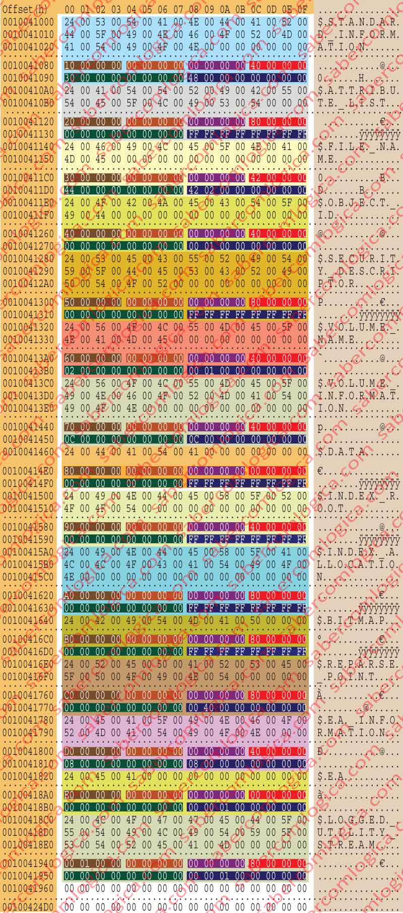
Once decoded our unique Data Run, we travel to the offset 10041000h to verify the data in the cluster which begins there and analyze them through the frame we put here together in figure 12-23 with the significate content of that cluster. To reduce this frame to a reasonable size we represent the lines filled with zeros between distant offsets with a single dotted line.
Surprise! The data of this file is what we are looking for since we began: the list and the definition of all the attributes.
Finally the List and Definition of all the Attributes

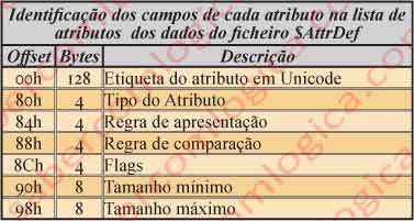
For the analysis of this frame we must use the table with the spaces occupation in figure 22, where each attribute definition occupies A0h, or 160 bytes.
We are going to read the fields of the 1st attribute designated in the attribute list in detail of figure 23, obtained with the hexadecimal editor according to the referred table.
This figure represents the hexadecimal editor representation of the $AttrDef file $DATA attribute, which as referred is the list of attributes and their main definitions.
The remaining attributes will be read briefly with the same assumptions.
The dotted line inside each attribute data represents all the lines filled with zeros.
The 1st attribute is the $STANDARD_INFORMATION
The first 128 Bytes from 10041000h to 1004107Fh contain the attribute name with the described text. Actually it occupies 42 Bytes (21 characters x 2 bytes).
The way how the text is read was already analyzed. Here we can compare its reading through Unicode (the text we just wrote for its name) and the reading through ANSI, represented at the right column of figure 12-23.
The 4 bytes from 10041080h to 10041083h designate the type of the attribute, 10h.
The 4 Bytes from 10041084h to 10041087h designate the display rule. For now (when we analyzed it) this is always 0.
The 4 Bytes from 10041088h to 1004108Bh designate the collation rule for ordering the records. For this attribute is 1 (Filename).
The 4 Bytes from 1004108Ch to 1004108Fh are Flags, which can define
- 02h – Indexed
- 40h – Resident
- 80h – Non resident
where the last two can combine with the first through the simple addition of their values. For this attribute is 40h what means it’s resident.
The 8 Bytes from 10041090h to 10041097h define the minimum file size. It’s 30h or 48 bytes, for this attribute.
The 8 Bytes from 10041098h to 1004109Fh define the file maximum size. It’s 48h or 72 bytes, for this attribute.
Using the same method we are now going to briefly analyze the remaining attributes from the list, giving special attention to what changes between them: The name, the type, the minimum size, the maximum size and the flag.
The 2nd Attribute is the $ATTRIBUTE_LIST,
- it has the type 20h,
- it’s non resident (80h), with
- the minimum size of 0 and
- the maximum size of FFFFFFFFFFFFFFFFh, corresponding to -1, what means that it’s maximum size is not limited.
The 3rd attribute is the $FILE_NAME,
- it has the type 30h,
- it’s resident indexed (42h), with
- the minimum size of 42h or 66 bytes and
- the maximum size of 242h or 578 bytes.

The 4th attribute is the $OBJECT_ID,
- it has the type 40h,
- it’s resident (40h), with
- the minimum size of 00h and
- the maximum size of 100h or 256 bytes.
The 5th attribute is the $SECURITY_DESCRIPTOR,
- it has the type 50h,
- it’s non resident (80h), with
- the minimum size of 0 and
- a non limited maximum
The 6th attribute is the $VOLUME_NAME,
- it has the type 60h,
- it’s resident (40h), with
- the minimum size of 2h (2 bytes) and
- the maximum size of 100h (256 bytes).
The 7th attribute is the $VOLUME_INFORMATION,
- it has the type 70h,
- it’s resident (40h), with
- the minimum size of Ch or 12 bytes and
- the maximum size of Ch or 12 bytes(fixed size in Ch).
O 8th attribute is the $DATA,
- it has the type 80h,
- it can be resident or non-resident (00h), because the files smaller than 1 KB, no name or only with DOS name can live inside the file, and indexed, with
- the minimum size of 0 and
- a non-limited maximum
The 9th attribute is the $INDEX_ROOT,
- it has the type 90h,
- it’s resident (40h), with
- the minimum size of 0 and
- a non limited maximum
The 10th attribute is the $INDEX_ALLOCATION,
- it has the type A0h,
- it’s non resident, with
- the minimum size of 0 and
- a non limited maximum
The 11th attribute is the $BITMAP,
- it has the type B0h,
- it’s non resident, with
- the minimum size of 0 and
- a non limited maximum
O 12º atributo é o $REPARSE_POINT,
- it has the type C0h,
- it’s non resident, with
- the minimum size of 0 and
- the maximum size of 4000h or 16384 bytes.
The 13th attribute is the $EA_INFORMATION,
- it has the type D0h,
- it’s resident (40h), with
- the minimum size of 08h or 8 bytes and
- the maximum size of 08h or 8 bytes (fixed size in 08h).
The 14th attribute is the $EA,
- it has the type E0h,
- it can be resident or non resident (00h), such as $DATA
- with the minimum size of 0 and
- the maximum size of 10000h or 65536 bytes.
The 15th attribute is the $LOGGED_UTILITY_STREAM,
- it has the type 100h,
- it’s non resident, with
- the minimum size of 0 and
- the maximum size of 10000h or 65536 bytes.
At the point where a new attribute description should begin we have only zeros what means the data reading has finished.
$BITMAP Attribute
As this is a non-resident and no named attribute it’s header is read through the table of figure 12-20, already used for the $DATA attribute.

This is the 4th attribute of the $MFT metadata file, and is the brown shadowed part of the hexadecimal editor representation in figure 34.
We made a detailed representation of that part individualizing the different header fields with different color shadows in figure 24. It must be read as previously we did for the $DATA attribute. So being:
- Its type is B0h.
- Its length is 48h, thus the next attribute begins at the offset 3148h + 48h = 3190h.
- It’s non resident.
- Its ID is 6.
- The initial and final VCN are 0, reason why it will occupy only 1 cluster.
- The offset for the data runs chain is 40h, thus beginning at the offset 3148h + 40h = 3188h
- The allocated size for it is 1000h = 4.096 Bytes, or 1 cluster.
- The real file size is 0EE0h = 3.808 Bytes
- The initial data chain size is 3.808 Bytes, thus it has not been modified.
- The data runs chain is as follows:
11 01 02 00 00 00 00 00
Let’s read the Data Runs chain.
- It has 1 byte which defines its size and that byte, the first after the half byte 1, has the value 01. Thus, it occupies 1 cluster.
- It has 1 byte which defines it offset in clusters and that byte, which comes right after the byte 01, has the value 02. This means that it begins right after the 2nd cluster, i.e. at the offset 2 x 512 x 8 = 8.192 = 2000h.
- This data run has 3 bytes ( 1+1+1 ) length. As the byte which comes next has the value 00, this is the last and only data run in the chain.
In short: The chain is compose by one data run which tells us that the file occupies 1 cluster and begins at the offset 2000h.
This type of attribute which, as the name suggests, is a map of bits, is usually used in 2 situations: in Index and in the $MFT file.
- In Index, the bits show the entries in use, each bit representing a VCN from the Index Allocation.
- In $MFT the bits field shows the MFT entries free or in use.
Why more this information, since each MFT entry has already signaled if it is or not in use?
One map of bits it’s a bit sequence, as many as the elements they intend to represent, where each bit represents one of each of the entities intended to be represented. It’s 1 or 0 condition designates if the represented entity is or is not in the state we intend to define.
For example: Let’s assume that we intend to represent the used or free condition of a set of 8 entries of an INDEX. We’ll have a map of bits (Bitmap) with 8 bits – 0 1 0 0 0 1 1 0 – telling us that the entries 6, 2 and 1 are in use and that the entries 7, 5, 4, 3 and 0 are free.
As in this case we are analyzing the $MFT file $BITMAP attribute, actually we are dealing with the MFT entries map of bits.
With a Bitmap representing the condition of those entries we avoid reading all the MFT entries in the disk to know each one condition, what surely would be extremely time consuming. It’s a lot quicker to verify a bits chain than an entire table.
The 2 next attributes have different header structures from each other, as they have different classifications according residency and name. So, we are going to present each one header and do its description inside each one of the attributes.
They are referenced in the . (dot) metadata file description, the root directory. The hexadecimal editor representation for that directory is in figure 35, where lie the values type which we are going to analyze for these attributes.
