NTFS Synopsis
Let’s recap, the sequence of logical operations of a computer boot with its bootable Volume formatted with NTFS.
- When the computer is powered on, the CPU is driven to run the program contained in the BIOS ROM Chip. After completing its routines, it drives the CPU to run the code contained in the MBR (Master Boot Record).
- This code reading, besides other actions, locates the HDD partitions, verifies what the active and bootable partition is and transfers the code execution to the code in its PBS (Partition Boot Sector).
- When the actions contained in this code are concluded the OS is launched and informed about the MFT (Master File Table) location.
- The OS identifies the MFT and its characteristics. By reading its first entries, the metadata files, the OS gets information about the MFT itself, about the Attributes which will be present in the files definitions within the MFT entries, in short, about all it needs to know in order to operate its file system.
- The OS accesses the Root Directory, itself a metadata file define in the first MFT entries, and is informed about the files and directories belonging to that root and each one entry in the MFT.In that moment the OS is in the base of the tree whose branches will take it to all the possible destinations within the File System. (See figure 54)
- By reading those entries, the OS gets the information about the beginning of all the possible paths to any file.The files are always referred by the path to them, their pathname.
A file pathname it’s its name within a path through the several nodes and branches in the tree leading to it and starting at the root. As is the case of the file we were looking for:
G:\Todas as Imagens\Diversos Pessoais\Diversos 1\Diversos 1999\Picture4.jpg
is the name or pathname given to the OS in order for it to find a given file (Picture4.jpg) in the File System. Therefore, when the OS is asked to find a file, its pathname is given to it. Then, the OS only has to find in the Volume the position of the several File System components which will lead it in that path.
Let’s rebuild in a simplified manner the path we followed to find our file, starting at the root, following the images in figure 53 and the steps signaled with lowercase letters, which we describe just after the figure.
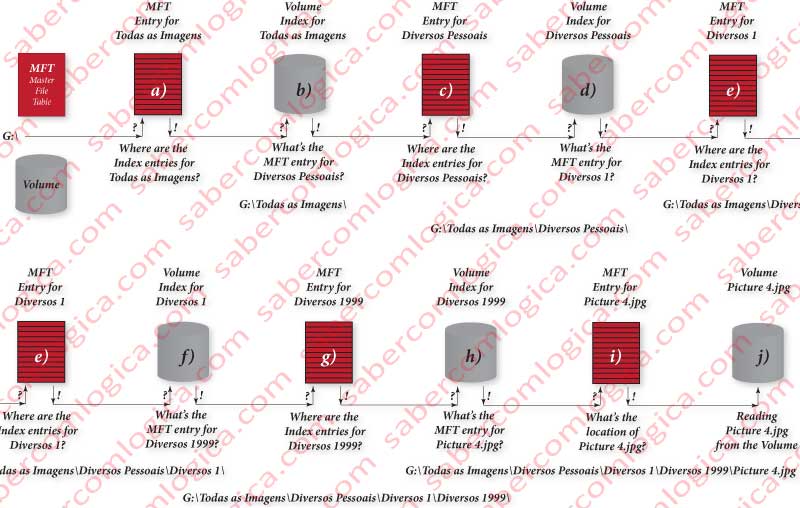
- a) The OS knows that “Todas as Imagens” is a directory pointed by the root directory or the first node in one the tree branches coming out of the root, and knows what its entry in the MFT is. Then it asks the MFT where is located the Index for “Todas as Imagens” in the volume.
- b) Once received that information from the MFT, the OS will find the Index for “Todas as Imagens”, which tells it all the nodes it points to and the branches leading to them. Then the OS chooses in that Index the node (directory) it’s interested in, “Diversos Pessoais” and obtains its entry in the MFT.
- c) The OS goes to the “Diversos Pessoais” MFT entry to know where its Index lies in the Volume.
- d) Then it goes to that location in the Volume to read the Index of “Diversos Pessoais” and verifies the MFT entry for the next note it’s interested in, “Diversos 1”.
- e) Then the OS goes to the “Diversos 1” MFT entry to know where its Index lies in the Volume.
- f) It reads the Index for “Diversos 1” to know what the MFT entry is for “Diversos 1999”.
- g) The OS goes to the “Diversos 199” MFT entry to know where its Index lies in the Volume.
- h) It reads the Index for “Diversos 1999” from the volume and obtains the MFT entry for our file “Picture 4.jpg”.
- i) Then the OS goes again to the MFT to read the “Picture 4.jpg” entry, to get the file localization in the Volume.
- j) Finally the OS goes to that location in the Volume where the file Picture 4.jpg is and does the action it intends over it.
These are the steps we can follow in figure 39 representing the several levels of indexation from the root to the file with Windows Explorer.
So, each time the OS has to find a file in the Volume it does all this operations?
No it doesn’t. To avoid it the OS creates a Cache for Directories where it keeps direct references for all the nodes (directories) through which it goes by. This Cache will be as much complete as bigger the RAM available for it. In optimal cases it becomes extremely quick after some searches.
It will be this way that, search after search the OS will know the nodes of the tree and all its branches, becoming very quick any search involving those nodes and their leaves or child nodes, which will also become part of the Nodes Cache.
Knowing this NTFS structured shape of organization, we can now understand that the MFT size does not influence the file system performance. When defined the path to a given file, its pathname, and given to the OS to find it in the Volume, once found its MFT entry, the OS has all the information it needs to access the file. And the path for the several nodes and leaves in the tree is already known by the OS if it has enough RAM.
We want to recall all the headers, attributes, index entries bit maps and other readings that were done to find the file and mount the tree in memory. With so many definitions about each file it’s easy its corruption if a record is interrupted before updating all the MFT information about the file, including the superior branches.
That’s the reason why $LogFile exists. Its purpose is to provide the atomic registration (while its success is not confirmed the OS doesn’t proceed with the subsequent executions) of all the file information in one only record. Subsequently, this register is read and its information distributed by all the records that were affected by the operation that focused on the file.
Every time the system boots the OS verifies the file system consistency by searching in the $LogFile for any record to be written in the Volume.
In figure 54 we can see a graphic simulation of the indexation tree which gives access to all the Volume content. Obviuously we only know the leaves of one of the multiple last level indexation nodes.
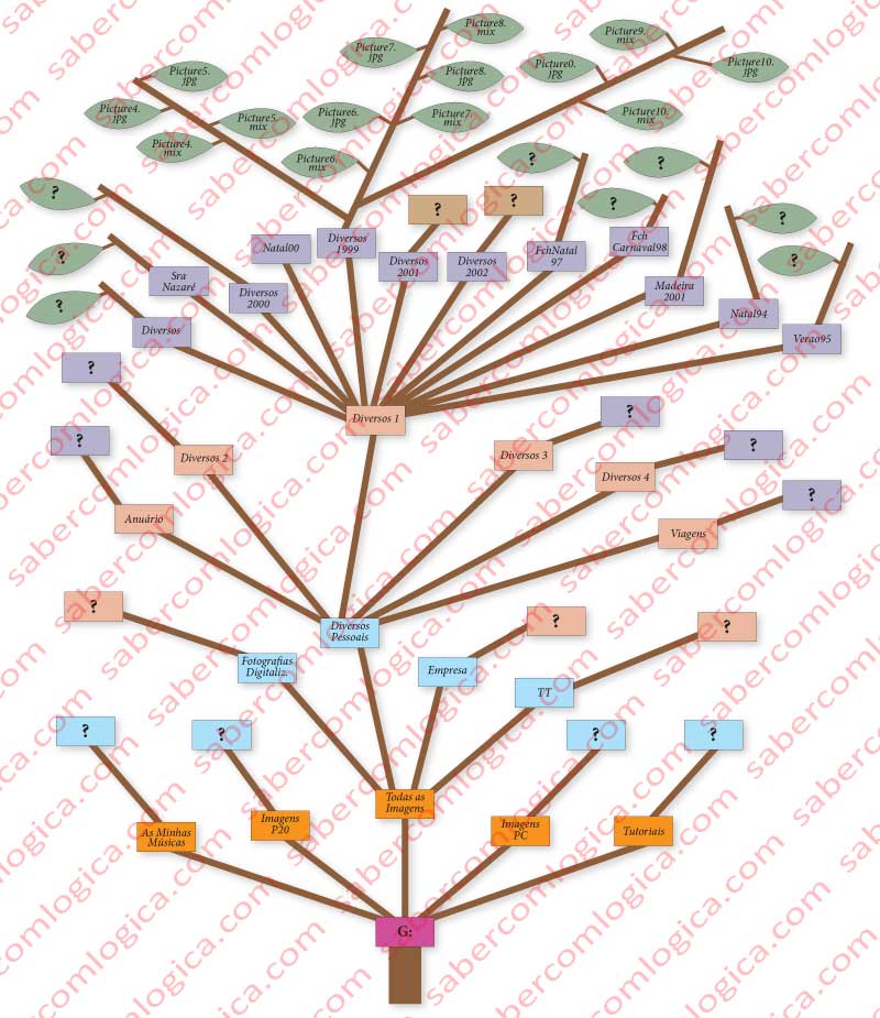
When going from the root to the leave we are looking for, the OS asks to each node in the path:
Whom are your children? Whom is your father?
The node tells it who they are and gives it their entries in the MFT, where it can find the information about each of them.
FAT (File Allocation Table)
The FAT (File Allocation Table) file system was conceived for the first PCs working under DOS (Disk Operating System). It was thanks to them that the computers management became accessible to the common citizen. As it was born in a prehistorical informatics epoch, its first version had the name FAT8 (8 has to do with 8 bits, the CPU bandwidth at the epoch) but quickly evolved to FAT12, the one we are starting to talk about.
But before we must understand what this name FAT really means, reason why we are going to give an idea about its basic composition.
As the name suggests the base of this file system lies in a File Allocation Table. Each cluster in a Volume has an entry in that FAT, i.e. if the Volume has 1,000 clusters the FAT will have 1,000 entries. Those entries are designed to describe the Volume clusters.
This said, FAT12 means that each entry of that FAT has 12 bits to do the clusters description. This way we could have 2¹² = 4.096 clusters identifiable (the Volume could have more but their existence would be ignored).
As the clusters size can go from 512 Bytes to 64 KB, the biggest possible Volume size supported by FAT12 was 4.096 x 64 = 262.144 Kb or 256 MB, what was a huge amount for the epoch.
Considering the possibility of using 64 KB clusters is the same as give up more than 50% of the Volume, due to the slack effect, previously described, corresponding to the non-used space of each cluster receiving files smaller than its size.
Imagine 10 files with 20 KB and 10 files with 70 KB. Actually their real size is 900 KB, but as each cluster can only contain 1 file or part of a file, the space used in the Volume will be of 10+10×2=30 clusters, or 1920 KB. The slack in this situation will be of 1020 KB.
As a solution for the HDD growth the FAT16 arose. This one is commonly known as FAT, as it is the standard for this system. With 16 bits per FAT entry, it could define 216 = 65,536 clusters, being possible to use Volumes with 256 MB (clusters of 4KB) until 2 GB (com clusters of 32 KB) or even 4 GB (clusters of 64 KB).
It was for Windows 95 2nd revision that the FAT32 arose, this one having 28 addressing bits (the remaining 4 being reserved for System indicators). This way it was theoretically possible to define 2²⁸ = 268,435,456 clusters.
We say theoretically because for this value we would have one Table with 268.435.456 entries with 4 Bytes each (32 bits), i.e. with the size of 1 GB, what is unthinkable for this table. We must not forget that for the system to be performant, the table should always be in memory. To reserve 1 GB of RAM only for FAT was unthinkable, especially given the smaller RAM size of on that epoch.
The Windows Server 2003, didn’t format in FAT32 Volumes with more than 32 GB, with sectors of 16 KB therefore the FAT having 2,097,168 entries or 8 MB in size, what was acceptable.
Of course this limitation was made by Windows Server 2003, when it already had the NTFS to format Volumes with higher sizes.
The size of this limitation is important to refer as it’s the one chose by the system itself and now we have at our disposal too the NTFS and HDD of much larger sizes.
Let’s see how FAT works. In a Volume formatted with FAT, the MBR (Master Boot Record) is identical to the one we’ve seen and the PBS (Partition Boot Sector) provides the following fundamental information for this system:
- The number of copies it keeps (normally 2 – original and security) of the Allocation Table.
- Its size and its copy size in sectors.
- The number of reserved sectors.
- The maximum possible number of entries for the Root Directory, normally 512.
We are describing the FAT16, as it will be easier for us to understand. The PBS for FAT 32 had to be extended, so occupying more than one sector, as the way for it to give the most possible information to the OS thus preventing the OS would have to read the entire FAT. This has substantially increased the PBS in size.
The FAT system is composed by 2 fundamental elements:
- The directory entries, where each file (a directory is a file too) has an entry describing it and telling the number of the sector where it begins. Each Directory Entry has 32 Bytes.
- The File Allocation Table, with 16 bits per entry. (FAT16)
Directory Entries
All the directory entries in the FAT file system have the name in the namespace DOS, thus with their name reduced to 8 characters plus 3 for the extension.
We are going to analyze these entries for a file with the name
“Este nome é só para demonstração.doc”
If the file name would have only 8 characters or minus and 3 for the extension the file description should be like the one in figure 56a, which in this case presents the file name reduced to 8 characters plus 3 for the extension, set the way we’ve seen before.
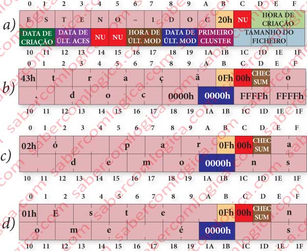
The name in DOS is described in ASCII, restricted to uppercase letters, only some special characters and numbers. When setting the name even the dot is ignored as it is implicit for the system and set in the right place between the first 8 and last 3 characters of the name.
If the file has a great name, as is the case, its representation is made by extending its description to more entries having the only purpose to describe its name, in our case 3 more entries. We’ll see further on how FAT does to tell the system that that entry has a long name.
The main directory entry stays exactly as it would be for a file with a short name, as represented in figure 56a and the meaning of the 32 Bytes composing the entry is the following:
- The first 11 Bytes (00h to 0Ah) are used for the name (8 for the name and 3 for the extension), the dot being ignored, as the system will include it.
- The 12th Byte (0Bh) defines the file attribute, composed by bit flags in a set of 8 bits meaning:
- 0000 0001 – Read
- 0000 0010 – Hidden
- 0000 0100 – System
- 0000 1000 – Volume label. The volume label is kept in the root directory
- 0001 0000 – Directory. It’s this entry which differentiates files and directories.
- 0010 0000 – Archive. This bit is used for incremental backups. Each time a backup is made this bit is set to 0. If the file is modified it’s set to 1 and the system will know it must be included in the incremental backup.
In our case its value is 20h, in binary 00100000, what means it’s a file and must be included in the next backup.
- The 13th Byte (0Ch) isn’t used by the FAT16.
- The 14th, 15th and 16th Bytes (0Dh, 0Eh, 0Fh) are used to define the described file Creation Time.
- The 17th and 18th Bytes (10h and 11h) are used to define the described file Creation Date.
- The 19th and 20th Bytes (12h and 13h) are used to define the described file Last Access Date.
- The 21st and 22nd (14h e 15h) Bytes aren’t used by the FAT16.
- The 23rd and 24th Bytes (16h and 17H) are used to define the described file Last Modification Time.
- The 25th and 26th Bytes (18h and 19h) are used to define the described file Last Modification Date.
- The 27th and 28th Bytes (1Ah and 1Bh) define which the first cluster for the described file is.
- The 29th to the 32nd Bytes (1Ch, 1Dh, 1Eh and 1Fh) define the described file size.
Well, and now tell me how does the system know that the file has a long name?
To tell the OS that it’s dealing with a file with a long name the FAT puts the name extension entries before the main entry and does it by the inverse order, i.e. from the last extension to the first.
In the name extension entries the attribute is set to 0Fh, or in binary to 00001111. The first 4 attribute flags set to 1 it’s an unexpected situation by DOS. This tells it to ignore that entry but that it must not use it as if it were free nor delete it.
The name extension entries for our case are represented in figures 56a, b and c.
In the name extension entries each character occupies 2 Bytes as it is described in Unicode (16 bits). Each name extension entry is composed as follows:
- The 1st Byte is the sequence number. It tells the name extension entry sequence within the full name (e.g. 01h, 02h, 03h, …). The last name extension entry will always have the bit 6 set to 1, thus being equal or bigger than 40h (40h plus that entry natural sequence).
- The next 10 Bytes (01h to 0Ah) are used for the name characters.
- The attribute (0Bh) is always set to 0Fh in a name extension entry.
- The Byte 0Ch isn’t used.
- The Byte 0Dh is used for the Checksum which verifies the DOS name accordance.
- The next 12 Bytes (0Eh a 19h) are used for the name characters.
- The 2 Bytes of the first Cluster (1Ah and 1Bh) are always set to 0000h.
- The last 4 Bytes (1Ch to 1Fh) are used for the name characters.
Each name extension uses 26 Bytes for the name characters. As the name is represented in Unicode, with 16 bits or 2 Bytes per character, each name extension entry represents 13 characters. The maximum number of name extension entries is 20, what allows representing the maximum of 255 characters.
At the end of the name are added 2 Bytes set to 00h, so a character set to 0000h. All the Bytes for name characters not used after this last one are set to FFh.
We’ve just seen how a directory entry is composed and, we’ve noticed that is the directory entry of a file that will tell us the first cluster where it is. Now comes the question:
How do we get to a file directory entry?
Let’s start at the Root Directory, the origin of all paths. The file entries in the Root Directory are limited to a maximum of 512. In the other directories there are no limitations. As it happened in NTFS here the directories are files too.
The Root Directory starts just after the FAT copy. That’s why the information provided by the PBS (Partition Boot Sector) are so important for the OS to define its start point. We can see in figure 55 the way how FAT records are distributed in the Volume.
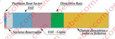
It’s the root directory which contains the first directories of a hierarchic chain identical to the one we have seen to the NTFS and represented in figure 54. In our example the root directory would be G:. This figure can as well represent the way we can get to a file in FAT.
One file is always referred by its pathname and its search is made through that pathname components.
Once found in the Root Directory the directory entry for our first directory in the path to our file, “Todas as Imagens”, that directory entry tells us the first cluster where the directory entries referring its content are.
When reading the content of the directory “Todas as Imagens”, we’ll find there the directory entry for “Diversos Pessoais”, which tells us the first cluster where the directory “Diversos Pessoais” is described.
And so on, until we find the directory entry for the file “Picture4.jpg, where is designated the first cluster for its description.
But this file takes a lot more than one cluster. The same way the directories description can take more than one cluster. Only the root directory can’t. And the directory entry only tells us the first cluster for its description.
So, how can we find the other clusters?
That’s precisely what the File Allocation Table tells us.
File Allocation Table
It’s time to analyze the File Allocation Table, the one which gives the name to the file system. Until now we know the first cluster containing the file. Let’s recall that the FAT has one entry for each Volume cluster, numbered accordingly to the clusters.
If we go to the FAT entry corresponding to that first cluster we’ll find there described the next cluster for the file and so on until we reach an entry referring FFFFh in 16 bits (FAT16).
So, let’s remember how you find a file in FAT: starting from the directory entry, which shows us the first cluster where the file is found, we must jump from entry to entry in search of the next cluster, until we reach the last one.
Therefore, the number we find in each FAT entry refers to the next cluster containing the file we’re looking for and to the FAT entry referring the next cluster after this one.
Let’s imagine a fragmented file with 22 KB. Supposing that each cluster has 4 KB this file will take 6 clusters for it which can be, for instance, in 3 different regions of the Volume. The OS will have to read all the FAT entries to know were the file is, cluster by cluster.
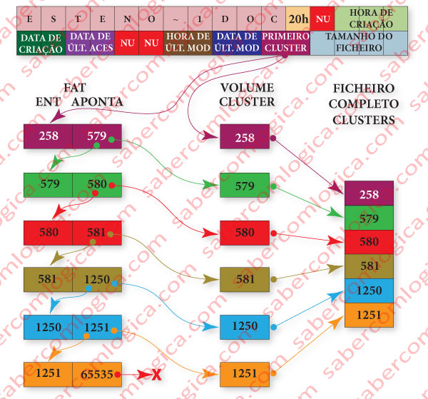
Let’s use figure 12-60 illustrating this described situation to better understand it:
Having the information about the file in first cluster provided by its directory entry (let’s suppose 258) the OS reads the referred cluster content and the corresponding FAT entry (the entry 258).
- The content of the FAT entry 258 (let’s suppose 579) represents the next cluster containing the file, which will be read by the OS as well as the content of the corresponding FAT entry (the entry 579).
- The content of FAT entry 579 (let’s suppose 580) tells the OS to read the cluster 580 containing one more piece of the file and also the FAT entry 580.
- The content of FAT entry 580 (let’s suppose 581) tells the OS to read the cluster 581 containing one more piece of the file and also the FAT entry 581.
- The content of FAT entry 581 (let’s suppose 1250) tells the OS to read the cluster 1250 containing one more piece of the file and also the FAT entry 1250.
- The content of FAT entry 1250 (let’s suppose 1251) tells the OS to read the cluster 1251 containing one more piece of the file and also the FAT entry 1251.
- The content of FAT entry 1251 (FFFFh or 65535) tells de OS that was the last cluster containing the file.
In short:
- The file is contained in the clusters 258, 579, 580, 581, 1250 e 1251.
- To read the file from the Volume the OS has to read the FAT entries 258, 579, 580, 581, 1250 and 1251.
We can easily understand that FAT is not adequate for large Volumes. And by large Volumes we can accept the maximum size of 32 GB established by the Windows itself to format a Volume in FAT.
But 32 GB is no longer in use. Except in small partitions or on floppy disks, , memory and flash memory cards or USB flash drives and on most portable devices such as PDAs, digital cameras, camcorders, media players, or mobile phones, all them supporting FAT. In those situations the FAT file system can be considerably quicker than the NTFS as this is a lot heavier due to the huge amount of parameters and records evolving each file. FAT file system doesn’t ensure file consistency and doesn’t provide security parameters to users and groups.
Except for these referred cases the FAT file system has been replaced by the NTFS file system:
- NTFS ensures file consistency.
- NTFS provides security at the file level by user and user group.
- In NTFS, once located the MFT file entry it’s found all the information about the file and its location in the volume, no matter what its size.
