
Selecting and Decoding Circuits
To move forward with the logic of computers, there are some concepts and logical circuits that we must take a look at first. A CPU is built via the interaction of these circuits, integrated within its own circuit. Arithmetic operations which have to be executed through iterative methods, use the interaction of these circuits. The Multiplexer or MUX, the Demultiplexer or DEMUX as examples of selecting circuits and the Decoder are circuits that we are going to analyze in this article.
All circuits that we are going to analyze are created with the combination of logical gates NOT, NAND, NOR, AND, OR, XOR and XNOR.
The Multiplexer
What it Does
The Multiplexer (MUX) can select one from several inputs through different combinations of selection bits. For each combination, only one input is selected.
Thus, 1 bit selects 1 of 2 inputs, 2 bits select 1 of 4 inputs, …, 16 bits select 1 of 256 inputs, …, N bits select 1 of 2N inputs. As we can see, the number of inputs which a MUX can select from is related to the number of possible combinations of the selection bits. The possible combinations of bits of a number N is 2N, therefore, these will be the number of selectable variables, having N selection bits. For example, with 32 selection bits, we can select from 232, or 4,294,967,296 possible inputs.
What is such a circuit good for?
If your imagination isn’t yet flying, we will give it a little jolt. Imagine, for instance, that you want to select a memory cell from billions. Wouldn’t such a circuit be useful for this?
Now, let’s suppose we want to choose between two values from different sub circuits, under the condition that a certain circumstance is, or isn’t, verified. This is a conditional decision that we must take based on the referred circumstances, and the analysis of the condition will return a logical true/false value, the selection bit, found somewhere else in another sub circuit, that will this way condition the MUX choice.
This situation will be verified, for instance, when we analyze the CPU. Now let’s see the following case of an abstraction.
A computer program is made of frequent conditional decisions, expressed by instructions like:
if (condition) DO THIS else DO THAT
which must be read like they would be in English.
The condition can be the result of analyzing the propositional expressions involving quantities and comparators, like human values, returning a true or false value, precisely the selection bit which will make the MUX choose between DO THIS if true (1) or DO THAT if false (0), the MUX inputs.
When we analyze conditions like x>0, or x>o AND x<10, or The man weighs 80 kg, or The man weighs more than 80 kg AND is more than 1.80 meters tall, we are doing propositional and predicate calculus. We are analyzing propositions that involve human quantities and comparators, returning a true or false value, 1 or 0, which is a Boolean value, or rather, a computer value.
A computer program is an abstraction, materialized in the computer circuits, to be executed, as the previous simple and basic relation shows. And as always, the complexity comes from the sum of its simplicities.
To generalize, we can say that at any moment, the MUX has the simple function of selecting between several possible values according to the values of the selection bits that it receives.
How it’s accomplished
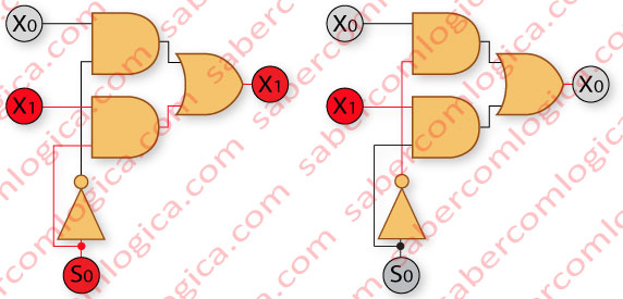
In Figure 1, we can see a MUX with one selection bit S0 and two inputs to select from, X0 and X1.
Each input is connected to an AND gate, together with the selection bit.
As we know, an AND gate returns 1 if both inputs are 1, else returning 0. So, an AND gate with the selection bit at value 1, will return 1, if the other input is 1, or 0 if the other input is 0.
In other words, an AND gate where the selection bit assumes the value 1 will return the other input value, 0 or 1.
With this in mind, if we want X0 to be selected when S0=0, we must connect S0 negation to the same gate as X0. This way, when S0 is 0, ¬S0 will be 1 and the value of X0 will be that AND gate output.
The same way, if we want X1 to be selected when S0=1, we must connect S0 to the same AND gate as X1. This way, when S0 is 1 we’ll have X1 value at the AND gate output.
So, we only have to make S0 or ¬S0 assume the value 1 in the AND gate where the input that we want to select, X0 or X1, is.
When S0 is 1, no matter what value X0 has, its AND gate output will be 0. When S0 is 0, no matter what value X1 has, its AND gate output will be 0.
This said, we can conclude that, at each moment, only one of the AND gates is selected, and has at its output the value of the selected input, the AND gate where the selection bit assumes the value 1.
As the circuit can only return one value, if we connect both AND gates to an OR gate, we ensure that the value of the selected input will always be at the OR gate output, whether it is 1 or 0.
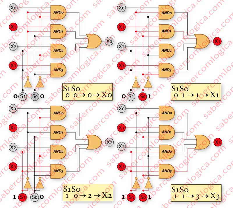
But a MUX can select from more than 2 inputs. Let´s look at the case of 4 inputs with 2 selection bits, as shown in Figure 2. The essential assumptions will be the same. Since we will have 2 selection bits, the AND gates will have 3 inputs, 2 for S0 and S1 and 1 for X0, X1, X2 or X3.
The 2 selection bits S0 and S1 have 4 different possible combinations (00, 01, 10 and 11), each one selecting one of the 4 variables X0, X1, X2 and X3, and must be connected as follows
- When 00(0), selecting X0, ¬S0 and ¬S1 to AND0.
- When 01(1), selecting X1, ¬S0 and S1 to AND1.
- When 10(2), selecting X2, S0 and ¬S1 to AND2.
- When 11(3), selecting X3, S0 and S1 to AND3.
This way, the selected input will be always the one with a decimal position identical to the selection bits decimal value.
As before, if one connects all the AND gates to an OR gate, this last one will always have at its output the value of the selected input.
Figure 2 represents how one of the 4 variables X0, X1, X2 or X3 is selected. The variables have the values X0=0, X1=1, X2=0 and X3=1.
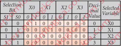
Figure 3 represents the truth table of this MUX and the correspondence between the decimal value of the selection bits and the selected variable.
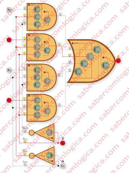
In order to better explain how the materialized circuit works, we have drawn a demonstration in Figure 4.
The Demultiplexer
The Demultiplexer (DEMUX) sets the value of one input variable in as many output gates as the possible combinations of the selection bits, one at each time.
It works the same way as the MUX when selecting the output gates. The input variable is connected to all the output gates. This way, the value of the input variable will always be in the selected output gate.
If we don’t connect any input variable to the output gates, meaning, if it doesn’t exist, then
- The selected output gate will always have the value 1, and all the others the value 0, when it’s an AND gate DEMUX without input variable.
- The selected output gate will always have the value 0, and all the others the value 1, when it’s a NAND gate DEMUX without input variable.
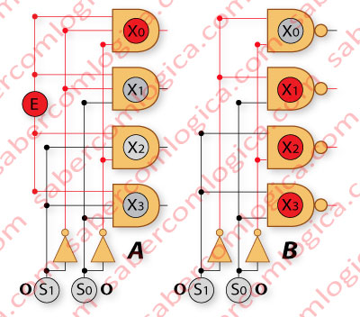
In Figure 5 we can see the logical circuit of a DEMUX 1-to-4 (1 input to 4 outputs) with AND gates (A), and NAND gates (B).
The NAND gate DEMUX has no input variable, as our purpose is to show the existence of one only output, precisely the selected one, with the value 0, as we can see, the DEMUX being active at 0.
If a NAND gate DEMUX has an input variable E, it inverts its value in the selected output gate. If E is 0, then all the outputs will be 1. If E is 1, then the selected output will be 0 and all the others 1. ¬E will be at the output of the selected gate.
The Decoder
A Decoder can, with a set of inputs, select a subset of outputs from a larger set of options.
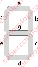
Let’s see this with a practical example, in Figure 6. A 7 segment display is used to show the digits in the display of a calculator.
Each digit in the display is composed by 7 segments, whose light can be turned on and off individually. At each moment, it displays the symbol represented by the set of segments that is lit.
The possible number of combinations of the 7 segments is 27, or 128, meaning it can represent 128 different symbols on the screen. But what we intend to show on the screen of the calculator are the 16 digits of the hexadecimal numeral system.
So, we only want 16 from 128 possible symbols, and we want only one active at each moment.
Let us look at Figure 7. If we use a DEMUX 1-to-16, without input variable and AND gates, we will give 1 of the 16 gates the value 1, and we will do this with 4 selection bits. Now, if we connect the AND gate output lines with the segments we want to light up, we will have the symbol we want in the display. In order to do this, we only have to map the segments with the lines of the AND gates.
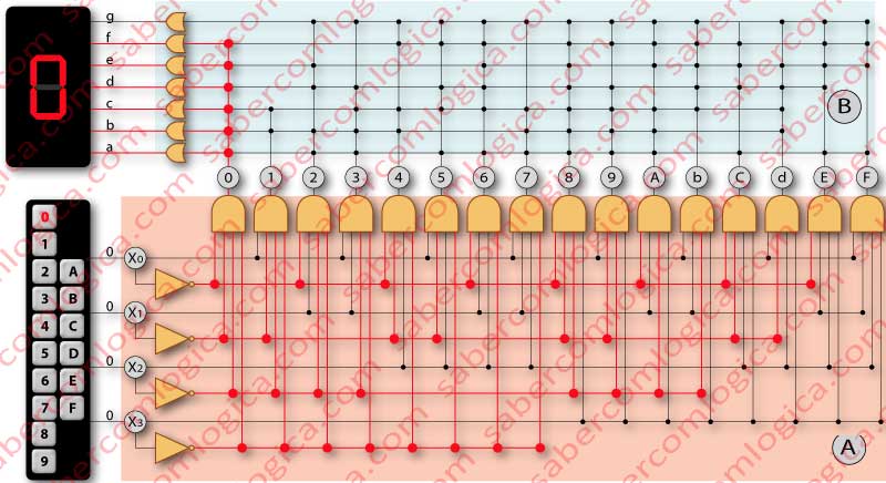
And here we are. With a set of 4 bits we can select a sub set of 16 symbols, from a larger set of 128 possible symbols. This was our initial definition that we intended to demonstrate in a practical situation. It’s done. This is a Decoder.
The logical circuit of our decoder is divided in two sections.
The first section holds a DEMUX with as many selection bits as necessary, in order to select a number of gates equal to the sub set options.
The second section holds a mapped circuit, where the lines that go out of the AND gates are linked with lines connecting to the segments a,b,c,d,e,f,g, according to the segments each one wants to light up.
Each one of the display segments is connected with the output of an OR gate. The inputs of these OR gates are the lines mapped with each one of the DEMUX output lines, who want to light up that segment.
These lines can go up to 16, when all the possible selections of the DEMUX want to light up that segment. In Figure 7, these lines are represented by a single line, due to evident lack of space, but actually they can be up to 16.
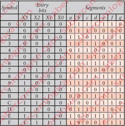
The mapping consists in establishing a fixed connection between the line that comes from the DEMUX, and the line that goes to the display segment, and is made according to the truth table of the decoder, represented in Figure 8.
We’ll see in the chapter about CPU one important application of this circuit, when decoding instructions. The method is the same as the one for this example.