
The Ethernet
Ethernet is a link layer LAN technology that since it was created is slowly enlarging its dominance, being today a totally dominant protocol, not only on Internet but in private LAN too.
Its success results from a great simplicity of its protocols. Ethernet is unreliable, despite using error detection codes for the sole purpose of discarding broken frames, so avoiding filling the network with useless frames, leaving the main work to TCP at the destination node.
Ethernet has always managed to follow and even surpass the speeds of its competitors.
Quickly spreading, the basic equipment of Ethernet
- NIC (Network Interface Card),
- HUB and
- Switch
become common usage equipment, substantially lowering their prices.
The 10 Gb Ethernet network is already deployed on the Internet 2 project, in large backbone networks.
Let’s see the rule of an Ethernet frame, as described in Figure 1, where the different fields have the following meaning:
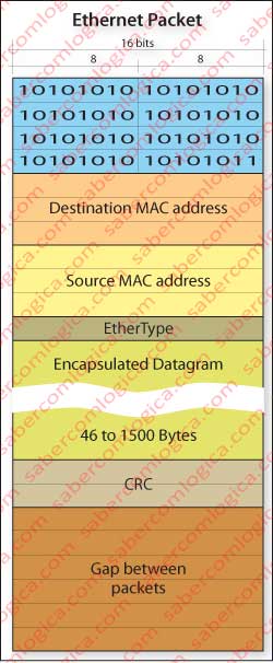
- Preamble – In the beginning of the frame there are 8 bytes of alternating bits 10101010 … till the 8th byte which ends in two successive 1’s, i.e. …01 011. The purpose of the preamble is synchronizing transmitter’s and receiver’s clocks, so that the receiver is able to distinguish 0’s and 1’s only by the clock frequency.
- Destination MAC address – Destination NIC (Network Interface Card) MAC address. It’s through the value of this field (48 bits) that the nodes who see the frame pass it to their upper layer level or forward it, if it matches their address, or discard it.
- Source MAC address – Source NIC (Network Interface Card) MAC address.
- Ethertype – It’s through this field that the frame is passed to the protocol which the encapsulated datagram is intended to. IP is not the only protocol. There’s ARP and a lot of others that we are not referring because they are not used on Internet.
- Data Field – This is where lies the datagram encapsulated in the frame. This data field can not be larger than 1500 bytes, therefore TCP calculates segment’s value so that being added the subsequent headers the datagram doesn’t exceed that size. If NEXT-HOP link doesn’t support that size the datagram is fragmented the way we have already seen. But this data field can not be less than 46 bytes, reason why it must be filled to this value if it is smaller. The receiver will know how to discard this filling through datagram header information.
- CRC – Cyclic Redundancy Check is the error detection code used by Ethernet. When the sending node assembles the frame CRC is calculated. When the receiver node gets the frame it calculates CRC the same way. If the result is different the frame is corrupted and therefore discarded.
- Interframe Gap – When a node finishes the transmission of an Ethernet frame it has to wait the time of issuance of 96 bits (12 bytes) in idle state until it can transmit a new frame.
When referring Ethernet equipment we mentioned Switch and HUB. Those are equipments that allow the interconnection of the various nodes within a subnet. These two devices forward frames, as the router does, but with the difference of just doing that – forwarding. Let’s make a description of each equipment.
HUB
The HUB, which we can see in Figure 2, is a network connector which operates at the physical layer. It is a common bus, that brings the nodes who are connected to it into connection. But it does more, regenerating the frames that it gets and repeating them in broadcast to all nodes that are connected to it. We have noticed that some articles refer to this broadcast, as a network broadcast to the last address of the subnet, i.e. xxx.xxx.xxx.255. We want to make clear that in this case the word broadcast has nothing to do with network broadcast or even link broadcast, but only with the fact that the package is placed on the bus being therefore accessible to all nodes connected to it (thus the word broadcast), without undergoing any change. Moreover, as already said, HUB works at the physical layer, thus being unable to change any part of the frame, not even to open it.
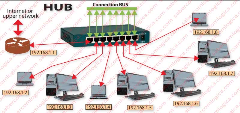
Thus, all nodes connected to the HUB are aware of the frame and verify if it is designated for them. The one to whom it is intended, what it verifies through MAC Address, collects it and passes it to the upper layers if it is a terminal node, or forwards it to a superior network level or to Internet if it is a gateway node. Only after the frame is collected by any of the nodes, other frames can be released throughout the subnet that connects to the HUB.
As all nodes dump packets into the same channel (the HUB bus) if the channel is busy transmitting one frame from one node to another, if someone sends a frame to that same channel, there will have a collision and both frames become unreadable , thus losing the transmission time spent on the two frames, the channel remaining unnecessarily occupied.
This is one of HUB major drawbacks . Although Ethernet uses the CSMA/CD (Carrier Sense Multiple Access with Collision Detection) protocol, any solution that is not subjected to collisions is preferable. Another HUB disadvantage is that its transmission is half-duplex, since there can be only one transmission in the channel, no matter in what direction. In addition, Ethernet restricts the maximum number of nodes and the maximum distance between two nodes in the same collision domain (the greater the distance, the greater the probability that a node begins transmitting before it senses that the another has initiated a transmission), what limits the size and characteristics of one HUB supported LAN.
With Switch negative trend in prices HUB use became obsolete, although it can still be found in some older networks, in some specialized applications or connected to routers on home networks, where the probability of more than one machine being simultaneously concurrent is low.
Because the CSMA/CD exists mainly for shared LAN, which is the HUB case, we think now is the best opportunity to address it, leaving the approach to the Switch for latter.
CSMA/CD Protocol
In bus topologies or HUB supported star topologies, collision likelihood exists and it’s bigger the greater the number of nodes involved. To properly address this issue Ethernet uses CSMA/CD protocol, acronym for Carrier Sense Multiple Access with Collision Detection. So let’s see how it does:
- A node listens to a channel before transmitting (carrier detection). When it realizes that the channel is free, it begins transmitting its bits, which spread in all directions along the transmission mean (if the bus topology) or in all directions in the HUB star topology through all the cables that connect to it .
- When a collision occurs, both nodes immediately abort the transmission (collision detection) and send a reinforce collision signal to confirm that both transmitters take effective knowledge of the fact and abort their transmissions.
A good method to be used in all TV debates in which different ideas are clashed with each other. Surely at the end all we should be much more clarified. Back to business.
So if a node starts to transmit only when the channel is clear, how can there be a collision?
The issue is the time interval required for a node to sense that the channel is busy, after another node starts its transmission. In the meantime the channel is free and any node can start a transmission which will inevitably collide with the other. In short, when two nodes decide to start a transmission almost simultaneously, a collision will occur.
After the collision detection and the emission of reinforce collision signal, both nodes enter an exponential waiting period.
And what is that?
This means that both nodes will choose between 2 possible values – 0 and 1 – and multiply it by the time it takes to transmit 512 bits. For example, for a 100 Mbps bandwidth 512 bits are transmitted in 5.12 μs (microseconds). Thus, they must wait 0 or 5.12 μs. With 50% probability they will choose the same value. In that case another collision will happen.
If so, now they will choose between 4 possible values – 0, 1, 2 and 3 – which they will multiply by 5.12 μs to find the time they wait. Now the probability that they choose the same value will be 25%.
And so on, till a maximum of 10 repetitions, according to the formula Time to wait = k*512 where k represents the value chosen from among a number of values equal to 2n, being n the number of repetitions, thus having 2, 4, 8, 16, 32, 64, 128, 256, 512, 1024 possibilities of numbers to choose as it is in the 1st, 2nd, 3rd, 4th, 5th, 6th, 7th, 8th, 9th or 10th repetition, being the probability of choosing the same number of 50%, 25%, 12.5%, 6.25%, 3.125%, 1.56%, 0.78%, 0.39%, 0.195% and 0.098% respectively.
If the collision still persists, the frame is dropped.
SWITCH
The switch, in opposition to the HUB, is free of collisions. However the switch is set to use the CSMA/CD when one of its interfaces is connected to a shared LAN channel, specifically one HUB.
Each switch port provides an interface itself, with storage capacity for frames, thereby allowing the transmission per frame for each destination. Thus, even if many frames arrive simultaneously to an interface from other ports on the switch, it has the capacity to store the various frames and send them one by one. It is therefore free of collisions.
When a frame arrives at a switch through one of its interfaces, it checks its destination by reading the destination MAC address of the frame and sends it to the interface that is connected to the node with that address.
And how does the switch know that?
The switch has a forwarding table where it registers the MAC addresses of the nodes connected to its interfaces. Earlier this table is empty, but as the switch is capable of learning, it fills that table as frames arrive to its interfaces until it is completely filled. The information contained in the frame header is all it needs to do this job.
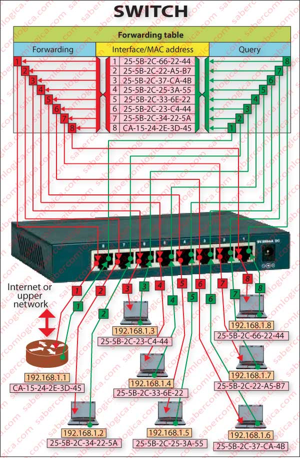
In Figure 3, we try to describe the relation between the switch and its forwarding table. Each node has assigned its IP adress, its MAC adress and the interface to which it is connected. The table has the relation between the interfaces and MAC addresses of their linked nodes.
The green lines represent the connection between the nodes and interfaces, and between them and the table for a query, e.g. when a node sends a frame, it is received on a switch interface and a query is made to the forwarding table for the recipient.
The red lines represent the connection between the forwarding table and the interface where the recipient is connected and between that interface and the recipient, e.g. the answer to the previous query and the frame’s forwarding to the node it was intended to.
And when the switch does not have the complete table and receives a frame with a destination MAC address that does not belong to the existing ones?
In this case, the switch sends the frame to all interfaces (minus the one from which the frame came) and the nodes that will receive the frame, if their MAC address matches the one in the frame header they pass it to the above layer, otherwise they discard it.
The switch is a connector of nodes who runs at the link layer level, in opposition to the HUB that runs in the physical layer. The switch reads the frames headers, forwards them according to the gathered information and populates its forwarding table. The switch can connect Ethernet links with different speeds. Reception and emission are made in different interfaces, each one respecting the characteristics of the link it is connected to.
The switch provides a dedicated connection in full-duplex with each node, as the Ethernet connector comprises two pairs of twisted wires that enable frames to walk on the same section in both directions without interfering with each other. Each connector is intended exclusively for one node (except when this connector is connected to one HUB – although the HUB represents a node to the switch, it will provide end nodes connected to it in a shared LAN). This capability is extended to each interface on the switch.
Full-duplex transmission, the possibility of interconnection links with different Ethernet speeds, simultaneous transmission of packets from different channels to other channels without collisions, market prices of equipment that fell almost to the level of the HUB, it is no wonder that the switch made the HUB become almost obsolete.
It was indeed with switched Ethernet that took place the great expansion of Ethernet networks in terms of increased speed and cost effectiveness of transmission capacity.
As switches can be interconnected at different levels, they are commonly used across subnets behind the gateway router. The speed relay that they offer is superior to any router, because they work at the link layer level and nodes’s MAC addresses are already partially known by them. We exclude from this statement the large private networks, because they have to be divided into many location or specialization subnets, and routers should be used for these subdivisions.