Transport Layer
So, here we are. The computer just pushed out of its applicational domain a message that is intended for the network. In order to push it out, it placed the message into an interface that we call socket.

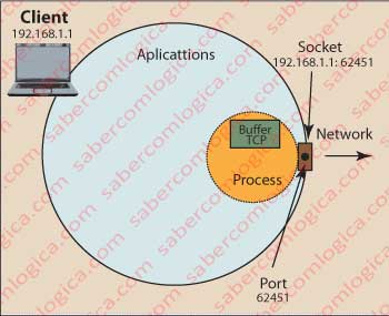
Socket is a communication interface between an application and the network. A socket is associated with a port and both are a way of computer communication with the outside world. The address of a socket is the combination of the IP address of the machine with the port.
A port is like an imaginary door on the breastplate of the computer applicational environment, to which will connect a process created by the OS from a network application.
Figure 1 tries to give a graphic picture of this relationship.
In a more formal definition, a port corresponds to a communications terminal point used by transport protocols TCP and UDP, to which is associated a specific process (remember, processes are programs that the OS is running under its control).
A port is identified by its number, an IP address and the transport protocol that uses it. The number of a port is defined by 16 bits and therefore goes from 0 to 65,535.
From 0 to 1021 are the so called “Well Known Ports”, e.g., Telnet service (port 23), SSH (port 22), SMTP (port 57), HTTP (port 80), DNS (port 53), FTP (ports 20 and 21), etc.
From 1024 to 49151 are registered ports.
From 49,151 to 65,535 ports are free for the user.
This means that, e.g., if a message with the HTTP protocol is sent to a computer with no existing pre-established communication, the message is directly sent to port 80.
The operating system is permanently listening for who knocks at their several doors to go see who is and give it to appropriate indoors.
Once made this small and important introduction, let’s now look at the services provided by the transport layer.
The word transport implies taking and bringing back. But it’s not the case for this layer. It effectively provides transport services, but it means logical transport services between processes on different machines. All the logic inherent to the transport guarantees, is based on this transport layer.
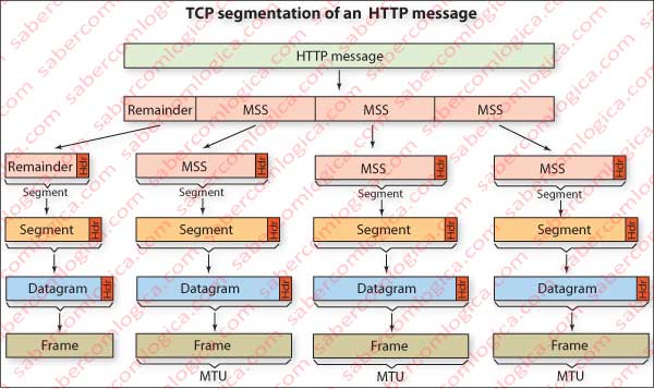
Let’s talk about packets here. The data link layer does not carry packets with the size that we want, but with a maximum size defined. In the case of Ethernet that size is 1,500 bytes, which gives rise to MSS (Maximum Segment Size) of 1460, if the TCP and IP headers have no options. These values are negotiated between the terminals during the presentation. The size of this packet is called MTU (Maximum Transfer Unit) and corresponds to the maximum dimension of the Frame.
To get the size in bytes of the HTTP message that each TCP segment may contain, the size of this layer’s header and those of the layers below should be removed from the MTU .
The HTTP packet must then be split into several packages, which will be named segment (the segment consists of the piece of HTTP message added with the TCP header), as many as required to complete the size of HTTP packet, but each one being not bigger than MSS.

Figure 2 illustrates graphically the division of the message packet in segment packets, division that will be kept all the way until its aggregation on the same layer in the recipient.
Let’s say that the transport layer deals with the packaging of the message into packets with the possible dimension, assures that all the message packets are delivered, that they are delivered by due order and that data transported isn’t corrupted.
Imagine small cars traveling on the network which have limited space for transportation, thus carrying only one sheet from our message at a time. So, as our message has four leaves, it will have to go in four small cars.
Say to the car drivers the destination address and put them on the road to travel intersection after intersection. This is the job of the next layer. But the road is heavily congested, drivers lead to enormous speed, some take one road others take another, some catch more traffic than others and linger, others have accidents and lose packets, but they keep arriving at their destination and deliver their sheets.
Now the problem arises. The sheets of the letter arrive out of order, some even don’t arrive. How does the recipient do to receive what we sent, in the right order and even see if there is a missing sheet?
Thanks to the logical transport services, the recipient process can determine this by opening all the packages and then solve the problem. Put the sheets in order and sense the lack of anyone to re-order it.
By this story, we can sense that the services of the layers below this don’t give any guarantee. Called Best Effort service, it’s goal is to deliver as much as possible in the shortest possible time. So does IP protocol which operates at the network layer, just below the transport layer, being only concerned with the delivery of machine to machine. Soon we will go there.
There are two protocols for the transport layer available for internet, which are TCP (Transfer Control Protocol) and UDP (User Datagram Protocol).
TCP is a connection-oriented protocol, providing services
- for multiplexing and demultiplexing (delivers the messages at the upper to the proper protocol),
- for error control or tampering of the packets content,
- for control of the effective delivery of all packages,
- to ensure that when passing packets to the layer above all they are there and in order, f
- or control of the network congestion (when it senses the network is congested it reduces the number of packets per unit time).
UDP is a connection-less protocol, providing services for multiplexing and demultiplexing and for error control, but nothing else, i.e., it doesn’t add any more controls to the bottom layer.
The TCP protocol is used by all applications that wish reliable data transmission, such as those created in HTTP, SMTP, FTP, e.g.
The UDP protocol is typically used for video applications, video conferences and generally any applications that are not extremely demanding in terms of reliability (note for example that some packet loss in video transmission is virtually undetectable by the user).
In these cases, regarding the simplicity of UDP transport protocol, the movement of packages becomes much faster.
Not delaying the delivery of packets by the transport layer to the application layer while one delayed packet doesn’t arrive, e.g., is important for real-time application. A video that is being received and viewed simultaneously, it is certainly much less affected by the lack of a packet than by the delay of all them.
But in order to understand this question, we must realize first what involves transport over TCP. As this is the protocol that will be used in our case study, references to the UDP will be generic and without details.
Let’s start by understanding how a TCP connection is established.
As mentioned above, the browser (the client) has pushed the HTTP packet to a socket. Once known the IP of the server, the browser sends a packet indicating that seeks to establish a connection with it. The server, in turn, responds with an ACK (ACKnowledge) packet and finally the browser sends another acknowledgment (ACK) packet. The first two packages do not have content, but the third can lead content.
An important note: When at this stage we speak of establishing a TCP connection it’s because this concept is critical to understand this protocol. However, each of these packages that we see moving from one place to another, will have to use the layers below to physically arrive at their destination. Layers which we will later discuss.
TCP Segment Rule
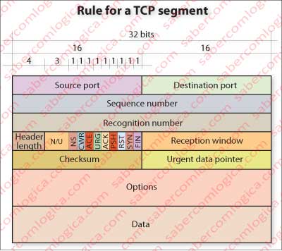
Let’s concentrate in the analysis of the constitution of a TCP header, so we can understand what we will discuss below. Let’s start by interpreting the terms of the frame in Figure 3, which represents the rule for a TCP packet with the different fields that compose it.

Source and destination ports – are the input and output interface of the computer through which TCP sends and receives data related to applications that are in communication. It’s possible to have many applications in communication simultaneously, each in a different port. This way TCP knows where to retrieve or place packets that it carries to or from a particular application.
Sequence number and recognition number are two numeric identifiers that will be used to guarantee of delivery and delivery order.
The reception window field is used for flow and congestion control.
The header length field is used by TCP to determine which portion of the packet contains the real message that it musts deliver to the application. The normal size of this field is 20 bytes, since the options field is not normally used.
The options field is used by the endpoints to negotiate several factors, including the size of MSS. As we said, this field is scarcely used.
Checksum is used to verify the data integrity of the package, i.e., detect if under the influence of external factors, casual or not, some or all bits have changed.
The ACK flag is used by the recipient to point out to the sender that it received a packet in conditions (the packet is defined by the sequence and acknowledgment numbers)
The SYN flag is used in the early establishment of communication packets.
The FIN flag is used when a host wants to terminate the communication.
The RST flag is used by a recipient when a packet hits him in a port that it has not in service. E.g., when trying to connect to a Web Server on its port 80 and the server in question is not a Web Server. In this case it sets the RST, in order to point out to the sender that it must reset the connection, because it is wrong. “I do not have here the service that you want.”
The PSH flag points out that a packet must be immediately sent to the application layer. E.g., it can be used in real-time applications over TCP, in order to avoid the retention of buffered packets, or Telnet applications that echo the sent digits one by one. Without this flag set they would wait for the buffer to be full to send the information to the application.
The URG flag points out that a packet contains urgent data. The urgent pointer field indicates the last byte of urgent data (which must start at the first data byte).
The flags NS, CWR and ACE only recently have been created, and when supported, they are used for congestion control in a more efficient way then previously was. The study of congestion control is a major task of the TCP.
Once known TCP segment header rule, we are now going to analyze how a TCP connection is established, how it is maintained and how it is finished. It should be recalled that although it’s TCP that determines the logic of the transmission, each segment, to travel the network, has to go through the layers below to be ready.
But, before we’ll do a short approach to checksum.
Checksum
There are several checksum algorithms, with several levels of accuracy and also complexity and execution times. The TCP checksum is undemanding, when viewed by today’s standards of safety, being however compensated by the methods of error control of the layers below, primarily in the link layer.
TCP checksum consists in adding the entire contents of 16 bit words in the segment, word by word, and then make an addition to this sum. The result is the Checksum value. The recipient makes the sum of all the words of 16 bits of the segment and to the total sum, it will add the Checksum value. The result will be a 16 bit word were all bits are 1. If it isn’t, something has changed in some way.
Let’s see an example, a packet with four 16 bit words:
1001110001010001
1100100010100101 0110010011110110
0010100111110100 0010100111110100 1000111011101010
1110010110010010 1110010110010010
4 words sum (Sender) 0111010001111100
Checksum (Complement) 1000101110000011
4 words sum (Receiver) 0111010001111100
Final Sum 1111111111111111
Binary’s sum is already familiar from some chapters above. We recall that one’s complement corresponds to the inversion of all bits, what is achieved by applying a XOR operator against a 16 bit word (in this case) with all its bits set to 1.
