
Wi-Fi – IEEE 802.11
Wi-Fi is certainly already familiar to many who may be reading these pages. It is available in Laptops, Tablets, Mobile Phones (using Wi-Fi in addition to the cellular network for Internet access), in almost all mobile equipment that can be connected to Internet. Likewise, due to such a large spread, the access points or WAP (Wireless Access Point), known as Hotsptots when of public access, also sense a large growth, being available in many public places like cafes, airports and railway stations, university campuses, schools, etc. even linked to home routers assigned by ISP to its clients, since those clients give their permission for public use (an IP and an interface different from their private ones) with the counterpart that they can use all the other WAP around the world.
The transmission is made by Radio Frequency (RF) in the frequency range from 2.4 to 2.4835 GHz, a range of 83.5 MHz. Domestic portable phones, Microwave, Bluetooth, and others who work in the range of 2.4 GHz are competing with Wi-Fi and can interfere with its transmissions. 802.11b technology, divides the 2.4 GHz to 2.4835 GHz frequencies in 13 channels, each spaced from the other 5 MHz. The first channel is centered on 2.412 GHz and Channel 13 in 2.472 GHz. The central position of channels 1 and 13 was chosen so that the 22 MHz signal frequency of each channel fits within the limits (11 MHz for each side of the center of the channel). With this arrangement only three of these channels can not have overlapping ranges, the channels 1, 6 and 11.
The implementation of 802.11g lowered the signal frequency to 20 MHz. The changed format of wave modulation allowed four non-overlapping channels 1, 5, 9 and 13. Obviously, emission through channels with overlapping ranges causes noise in the overlaid channels destroying both transmissions. Currently it is advisable to use channel 1, 5, 9 and 13. However most of the existing equipment still comes pre-configured for three channels 1, 6 and 11, but could (and should) be reconfigured for the 4 channels 1, 5, 9 and 13.
A Wi-Fi 802.11 network is composed of several wireless stations and a WAP (Wireless Access Point), featuring interfaces WNIC (Wireless Network Interface Controller). WAP is in turn connected to a wired Ethernet network, from which it binds to the global network.
To this kind of network is given the name of Single Hop Wireless Network Infrastructure Based. The set composed by all the various wireless stations and the WAP is called BSS (Basic Service Set), which is the basic building block of an 802.11 LAN. The area covered by a WAP is called BSA (Basic Service Area), which should not be confused with BSS. When any device with a WNIC (e.g. a laptop) is turned on in a place belonging to the BSA of various WAP, before being able to communicate it has to choose one of them to establish an association. Having made the association with one of the WAP, with whom he establishes a kind of virtual line, it now belongs to that WAP BSS.
Connecting a STA and a WAP
The connection of a STA(Station) to a WAP goes through several phases, which we are going to describe:
Discovery of a wireless network:
Passive method – the various WAP periodically emit a beacon comprising a packet flag of their presence, providing its ID or SSID (Service Set Identifier) and the technical elements needed for the STA to connect with WAP (Wireless Access Point). The STA chooses the one whose sign is more powerful, assuming that all WAP are from the same subnet. If not and STA is in a public area with different networks WAP, it will have to choose the best signal among those who belong to the network that it is allowed to connect to.
Active method – The STA sends a packet with a discovery message (probe request) and the WAP that are within range respond with a reply frame to the discovery message (probe response) that contains information identical to the beacon, i.e. all that STA (Station) needs to connect to the WAP (Wireless Access Point). This method allows the STA to specify in the discovery message the SSID (Service Set Identifier) of a specific WAP and then only that WAP will respond if it is in it’s range.
If you work in Windows, you’ve certainly noticed that when a notebook interface WNIC (Wireless Network Interface Controller) is connected, a list of all WAP whose BSA (Basic Service Area) cover the notebook area, in descending order of signal intensity, private and public, so that the user can choose the best among the possible (those for which it has contractual access) from the list.
Authentication:
Since the STA is able to connect to one of the attainable WAP, it begins the authentication phase with it. This authentication is usually done by password and can be quite complex when using digital certificates in certain companies or university campuses.
The STA sends a packet with an authentication request containing the necessary elements for this purpose and the WAP, after conference and confirmation that the STA is able to be associated sends an authentication response packet granting or not the right to proceed.
If the right to proceed is granted the STA begins the next phase.
Association:
The STA sends to the WAP a request for association with the necessary technical elements and the WAP SSID. Then the WAP sends an association response packet with the STA ID associated with the SSID, the transmission rate of the WAP, and a field indicating success. in other words, the WAP tells the STA that the connection was well succeeded and that the STA now has the number x in its BSS (Basic Service Set).
After the association the connection operation is completed. The STA is able to send packets to the WAP. Probably the first message that it is going to send is a DHCP discovery message packet in order to obtain an address on the subnet of the WAP. From that moment on, Internet sees the STA (Station) host as a node on the subnet of the WAP (Wireless Access Point).
Maintaining the Connection
At any time the STA or the WAP can break the connection, using for the purpose disassociation or logout messages.
If only one disassociation message is sent, the STA will no longer be associated with this WAP but it will remain authenticated in it.
To reconnect, the STA must use the reassociation request messages and get a reassociation answer from the WAP.
A situation like this can happen for example when a STA moves within the same subnet (e.g. an university campus) from one WAP BSA (Basic Service Area) to another WAP BSA. Through the described messages the STA can change WAP without losing its network connection.
Link Layer Acknowledgement
In wireless communications, as the corruption of the bit value is more frequent than in transmissions by wire, ACK was introduced at the link layer. Thus, for each frame sent, the sender waits for an acknowledgment (ACK) frame (in the case CRC check was OK) from the recipient. Failing the ACK, after a given period of time it resends the same frame, and so on. If the ACK remains failing, after a set number of retransmissions the frame is discarded.
CSMA/CA Protocol
CSMA/CA is the acronym for Carrier Sense Multiple Access With Collision Avoidance. Notice that here we say Avoidance instead of Detection as we did in the Ethernet. In a BSS (Basic Service Set) there will always be several STA associated with the same WAP simultaneously attempting to transmit, reason why Wi-Fi transmissions use a random multiple access protocol identical to the one in Ethernet. Carrier sense, works as previously described, i.e. a node is listening to the channel before it starts a transmission, and only starts it once verified the channel is free. So far Ethernet protocol meets the specificities of WiFi transmissions.
Transmissions made by WNIC (Wireless Network Interface Controller) are half-duplex, i.e. when an STA transmits it doesn’t listen and when it listens it doesn’t transmit. Making this interface with full-duplex capabilities would be extremely expensive, beyond the fact that in this situation the ability to listen to a collision is very low, given that the signal of existing activity on the channel during a transmission is very weak compared to signal from the transmission itself. Thus, collision detection of Ethernet protocol was abandoned. When it happens, the sender only will be aware of it in the lack of an ACK for the sent frame. In case of any collision, the transmitter keeps sending the entire frame, what is a huge waste of channel time. In this perspective was chosen to create instead a collision avoidance protocol in order to prevent collisions.
If a node intends to send a packet and verifies that the channel is clear, it waits a short period of time called DIFS (Distributed Inter-Frame Space) and starts its transmission. If the channel is busy, it chooses a random value and when the channel is free it starts a countdown, starting the transmission as soon as the countdown reaches zero.
Why this operation before transmission?
Let’s see. Let’s assume that a node is transmitting and that two others have frames to send. Both are ready to begin their transmission as soon as the channel is clear. So being we would certainly have a collision. But, as both chose random values and enter in countdown, one will begin transmission before the other, what will cause the other to sense the channel as busy and stop its countdown until the channel is free again, thus avoiding a collision, which will only happen if the chosen values are equal.
If a collision happens, the transmitting nodes, once the respective frame ACK is not received, will restart the process by choosing a random value, now from a larger range, what will make collision less likely to happen. In the meanwhile, as the channel is free, other senders may initiate transmissions, thereby interrupting the process of counting down of the first two nodes, so increasing the range of chosen values and consequently increasing the separation between the start of their transmissions.
And in the case where the two STA (stations) can access the WAP but can not listen to each other due to the existence of an obstacle?
Therefore, any STA has the chance to reserve the channel for its transmission by sending a RTS (Request To Send) frame to WAP (Wireless Access Point), which in turn responds with a CTS (Clear To Send) frame to all STA in the BSS (Basic Service Set). Let’s put this in parts:
- RTS frame requests the WAP an exclusive channel for a certain period of time required for packet transmission.
- CTS frame gives authorization to the STA to start transmission and indicates to other STA that must cease all transmissions during the period of time required for the first STA.
This possibility gives a great guarantee that frame will be Acknowledged, but will delay transmissions and spend lots of resources. So is normally only used for very long frames, being its size defined by each interface.
Power Saving Mode
STA, as they normally are mobile equipments, are very dependent on battery usage, so often placing themselves in power saving mode, for instance turning off the radio, a large energy consumer. The STA notifies the WAP of that fact by sending a null function frame with one bit stating that it will go into PS (Power Saving mode). Then it turns off the radio, only periodically exiting PS to hear the WAP beacon.
Thereafter the WAP saves all incoming frames for that STA. Thereof, through the beacon that the WAP transmits approximately every 100 milliseconds, it alerts STA to that situation including in the beacon frame the ID of STA that have kept frames waiting to be received by them. When the STA wakes up, by reading one of these beacon frames it realizes that it has frames to receive. Thus it sends a frame stating PS-Poll (Power Save Poll) to the WAP. In other words, the STA says to the WAP that it woke up, realized that it had frames to receive and asks it to send them. Then the WAP sends to the STA all the frames that it has kept for it in its buffer.
Rule For an IEEE 802.11 Frame
Since we have already addressed the key issues for its understanding, we can now analyze the rule for an IEEE 802.11 frame, which we can see in Figure 1, where the first row of the table corresponding to the first two bytes of the header (16 bits) is divided as shown:
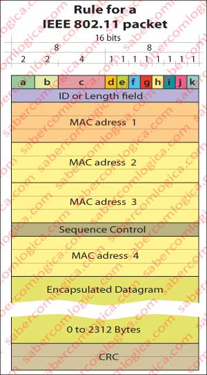
Frame Control Field
- a) Protocol version (2 bits) – currently is zero.
- b) Message Type (2 bits)
- Maintenance (00)
- Control (01)
- Data (10)
- c) Subtype posts (4 bits)
- b) Type = 00 ↔ Maintenance
- Request Association (0000)
- Response Association (0001)
- Request for reassociation (0010)
- Response reassociation (0011)
- Probe Request (0100)
- Probe Answer (0101)
- Beacon (1000)
- ATIM (1001) – When the WAP communicates that it holds in its buffer frames for STA which are in PS.
- Disassociation (1010)
- Authentication (1011)
- Deauthentication (1100)
- b) Type = 01 ↔ Control
- PS-Poll (1010)
- RTS (1011)
- CTS (1100)
- ACK (1101)
- b) Type =10 ↔ Data
- Data (0000)
- Null Function (0100) – No data
- b) Type = 00 ↔ Maintenance
- d) To WAP (1 bit) – When set, the message is directed to the WAP.
- e) From WAP (1 bit) – When set the message comes from the WAP.
- f) More fragments (1 bit) – When set there are more fragments belonging to the same frame. Used when a frame is fragmented to reduce its size.
- g) Relay (1 bit) – When set it is a retransmission of a frame already sent. Allows the receiver to understand when a frame is a duplicate in sequence of a lost ACK.
- h) Energy Management (1 bit) – When PS (power saving mode) is activated.
- i) More Data (1 bit) – When the WAP’s buffer has more frames, kept after PS-Poll, to send
- j) WEP (1 bit) – The package body is encrypted in accordance with the WEP (Wired Equivalent Privacy) algorithm which is deprecated.
- k) Sort (1 bit) – When set the frame is being shipped with the strict ordering service. There is only one protocol that uses these services and it’s not used by TCP / IP model.
Duration / ID
This field can have two different meanings depending on the frame type:
- In frames with PS-Poll message it’s the STA ID o .
- In other packages the time necessary for transmitting the frame.
Control Sequence
This field is divided into two parts:
- The first 4 bits represent a frame’s fragment order if such fragmentation exists.
- The remaining 12 bits represent a sequence number identifier of a frame with functions identical to those described for TCP.
CRC
Cyclic Redundancy Check is the error detection protocol that we have seen in Ethernet. With higher reason it is used here as the probability of frames’s bit changes is much greater.
Addresses 1, 2, 3 and 4
The value of these addresses varies depending on the values of 4.(to WAP) and 5.(from WAP) bits of the control field. There are four possible scenarios of transmission that are reflected in the value of bits d and e, from which we will mention the two which are related to the type of network we are analyzing, wireless networks with infrastructure. The other two relate to ad hoc networks and communication between WAP that don’t fall within the networks with infrastructure that we are analyzing. In either situation address 1 is always the destination address and address 2 the source address. According to bits 4 and 5:
10 – The packet is sent from the STA (Station) to the WAP (Wireless Access Point). Address 1 is WAP’s address and address 2 is STA’s address.
01 – The packet is sent from the WAP to the STA. Address 1 is STA’s address and address 2 is WAP’s address .
So far nothing new. Evident deductions regarding what was previously said. Our discussion will now evolve to match what address 3 represents. Let’s remember that we are talking about networks with infrastructure, i.e. WAP sends and receives frames to the router of the subnet to which they belong through a wired network, so using Ethernet. We are in presence of a network interconnection. A frame leaves the STA with IEEE 802.1 format, is received as such by the WAP, which has to convert it to an Ethernet frame and send it to the gateway router of its subnet. Likewise the WAP receives the frame from the router in Ethernet format and has to convert it into an IEEE 802.11 frame format to send it to the STA.
Let’s imagine that some device on the Internet sends a frame to the STA. This frame will arrive at the gateway router of the STA subnet, who knows the address of the STA, with this address inserted in the destination address of the datagram. Once knowing the IP address, the router uses ARP to discover STA MAC address and populates the Ethernet frame with its own MAC address as the source address and WAP MAC address as the destination address.
Through the link-layer the frame is forwarded to the WAP responsible for that STA. Then the WAP fills an IEEE 802.11 frame by placing STA’s address as address 1 (destination), the WAP address as address 2 (source) and the address of the gateway router as address 3. And it sends the frame to the STA.
Now the MAC address of its subnet gateway router is known by the STA. When the STA replies to the message it builds an 802.11 frame placing the WAP address in address 1, its own address in address 2 and the gateway router address in address 3. When the WAP converts the 802.11 frame to an Ethernet frame, it places address 3 at the destination address and its own address at the source address. In conclusion, for transmissions to and from outside the subnet, address 3 represents the subnet gateway router address.
Wi-Fi is a local area (LAN) wireless computer networking technology. Ethernet is a family of computer networking technologies for local area networks (LAN) besides others as MAN (Metropolitan Area Network). AS we’ve just analyzed this two LAN technologies we think it’s time to show what’s a LAN Topology.
LAN Topology
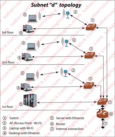
Now that we‘ve ran all the path of the packet, we can tell something about a LAN Topology, for instance the one of the subnet d of Area 1 of SA4 in the Figure used in routing which could have the shape shown in Figure 2.
A network topology is its layout, it’s the way how its nodes and terminals are interconnected, it’s the definition of those nodes and terminal equipments.
The BUS topology , widely used in the past corresponds to the connection of all the hosts, including the host responsible for the public network connection, to a single coaxial cable with terminators at both ends. This topology is practically obsolete although it is still used by some Ethernet networks.
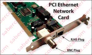
The old Ethernet cards have BNC and RJ45 connectors. BNC plugs are similar to those of TV set antenna. RJ45 plugs (Ethernet) are similar to the telephone ones, as shown in Figure 3. BNC plugs were used for BUS topologies.
The Star topology, is the one where all hosts have an independent connection to a HUB or to a Switch.
In the case of a Star topology connected to a HUB, we end up having a Star topology that becomes a BUS topology, because the hub is nothing more than a BUS where all the cables coming from each host are connected. Instead of the BUS being a cable that goes through all the hosts, it is a small BUS in a device to which all hosts are connected. This is just what is graphically represented in the Figure 2 of the previous article.
In the case of a Star topology connected to a Switch, the frames sent from each host don’t meet each other, because the switch input interfaces for each host have an independent buffer in which it puts received and not yet sent frames. Thus, it has the capability to forward any frame to any destination separately. And for each destination it delivers them one by one, avoiding collisions. This is what we can see in Figure 3 of the previous article.
It’s time to move and make a slight approach to the Physical Layer, to put an end to our journey.
The Physical Layer
The physical layer is responsible for the modulation of bits according to the physical media on which the frame will be transmitted. Electromagnetic waves modulation, electromagnetic, optical, laser impulses, etc. It is a process that has more to do with aspects of electro-technology than with computers, so escaping the scope of this work. The same frame can go through several physical means of communication. Its content will always be the same. The headers for Ethernet and Wi-Fi which have been seen, always remain the same.
Outside the wireless world, transmissions will always be read by the terminal through Ethernet cards. Therefore, between routers, the bits to be modulated according to the physical mean between them, include the Ethernet header, as their Link interfaces will be Ethernet cards. In the networks terminals they can find protocols different from Ethernet (very unlikely), but it was not the purpose of this work to cover such cases.
The same frame can be sent, for instance, through:
- Wi-Fi (micro RF pulses whose particular composition represent a bit’s value) from the STA (Station) to the WAP (Wireless Access Point).
- Ethernet (usually by Manchester encoding) from the WAP to the gateway router that has associated with it a transmission modulator to
- Coaxial cable, through which the transmission follows to the exterior of the building where it is received by a converter from coaxial cable modulation to modulation for
- Optical fiber. And it goes like this until an Area border router that converts the fiber-optic modulation for modulated
- Microwave (microwave), so that it goes to the AS border router. There it is converted from microwave modulation to modulation for transmission by
- Satellite, which takes it to the recipient’s AS border router.
From there they follow the reverse route (microwave, fiber optic, coaxial cable, Ethernet and Wi-Fi) until the recipient and repeat the two routes with the reply to the message. Each of these transmission methods corresponds to a shape representation of the bits in accordance with protocols that allow the sender and receiver to understand them.
Conclusion
But, for now we stay here.
The composition of each frame through the several layers, the way it is sent from source to destination and back have been decomposed.
This is what happens with the thousands of frames that compose a page you asked for and received in milliseconds or maybe seconds in your computer.
We hope now you become more comprehensive with your friend when it takes a little longer to serve you