
From Analog to Digital -The Photosite
Image Capture
Images like, for instance, the one that we can see on the screen while producing this work, are already created in digital format.
For instance, games’ 3D simulation images are produced by the CPU according to the game’s specific software in digital format, and sent to the Graphics Card for all the graphical operations they require. As such, they are normally vectorial images (resulting from the graphics drawn by complex mathematical functions) that, after being executed, only need to be rasterized (converted to pixels) in order for us to be able to see them.
But the images that we grasp, visually, in our living space are analog, meaning that the information through which we sense them is given to us by our vision in line with our brain, and that they have nothing of binary.
This information corresponds to wavelengths of light that are received by the photosensitive cells in our retina.
And it is precisely this way that the image information gets to the optical system of a digital camera.
So, how do digital cameras already provide us that same image, in digital format?
That’s precisely what we’ll try to understand next.
The picture is received inside the camera by means of opening the shutter, prepared by the optical system. So far, all is the same as in an analog 35 mm film camera.
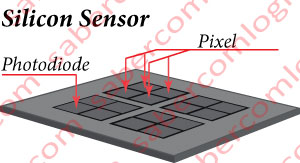
Only that, instead of a film, we have a sensor composed by a silicon chip, as shown in Figure 1. The purpose of this sensor is to capture the light and its identification. The remaining data processing and storage is performed separately. When the camera’s shutter opens, the sensor is exposed to the light of the image we want to capture.
The sensor’s chip is composed of photodiodes. The photodiodes are areas of the sensor’s chip, with transistors that react to light exposure, converting it into electricity (electrons) in an amount proportional to the intensity of the captured light.
But the photodiodes only capture the light intensity, without differentiating the color. To reconstruct the color we need the information of each RGB color’s light intensity. How is it?
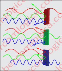
In order to identify each type of light, the photodiodes are covered with color filters that only let through one of the three RGB primary colors, as shown in Figure 2.
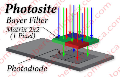
The most used filter to cover the photodiodes is the Bayer mosaic, as shown in Figure 3, comprised of mosaic filters arranged in sets of 2×2 arrays, 1 for Red, 2 for Green and 1 for Blue, resulting in 4 filters, one for each photodiode, the information of each pixel given by 4 photodiodes in total.
This composition results from the study of the optical response of the human eye cells. Our eye’s retina has two kinds of optical cells:

- The Cone cells, and main receivers, are sensitive to Red, Green and Blue by differentiating between the wavelengths that characterizes each of the basic colors. Red is a long wave, Green is a medium wave and Blue is a short wave. The cones are located at the center of the retina.
- The Rod cells, which are located on the outskirts of the cones, are sensitive to green and mainly responsible for peripheral and night vision.
Through this description, we can easily perceive how the human vision is dominated by RGB.
When we mentioned 2×2 mosaic matrices sets, we mentioned the corresponding pixel information which, as we have seen, is defined by amounts of R, G and B. Therefore, when we say that a particular camera has a resolution of 5 Mega pixels, this means that its sensor has 5 million 2×2 matrix mosaics, with the respective photodiodes underneath, equaling 20 million photodiodes.
The graph in Figure 4 is intended to illustrate what we have just described. The light, in its full spectrum, focuses on the mosaics, which only let through, in each case, the wavelength that the mosaic doesn’t reflect.
The photodiodes placed underneath the mosaics, will generate an electric intensity (a quantity of electrons) equivalent to the intensity of the light that is let through, or in other words, an intensity equivalent to the saturation of that color.
This electric intensity is reported by the sensor to a microprocessor, which is responsible for converting into binary the analog information it receives.
The graph in Figure 1-17 is intended to illustrate the composition of the microprocessor, according to the functions performed during the image digitalization process, after it receives the information from the sensor. The following steps are performed during this conversion:
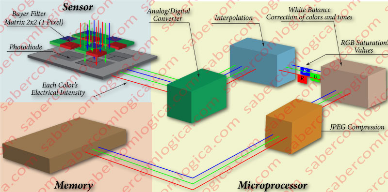
An Analog/Digital Converter transforms the analog information received from the sensor (the electric intensity) into digital information. The electric intensity corresponds to a given percentage of the expected maximum, 100% being the maximum of the representable range in 8 bits. Once calculated the received percentage, it’s assigned the corresponding value, in a range of 0-255. For example, 20% corresponds to the decimal value 51, and to the binary value 00110011.
Interpolation of the converted binary information that comes with 4 different intensities assigned to it, in order to obtain the corresponding RGB value. For this purpose, huge complexity algorithms are used, converted into mathematical functions that are specific to each manufacturer and filter matrix.
The silicon’s sensitivity to the color is not equal to that of the human eye. Thus, through complex algorithms specific to each brand, converted into mathematical functions that carry out the necessary calculations, the RGB values so far obtained experience the following:
- A white balance correction based on the closest, pure, white area.0
- A color correction that will approach the color values obtained by the silicon, to the color values seen by the human eye.
- An anti-aliasing correction, whose function is to reduce the aggressive, characteristic transitions, digital images exhibit in high contrast areas.
- Several other small corrections that will always attempt to alter the image to be as close as possible to our reality.
The set of pixels that composes the image will be compressed to JPEG format, or another, or even not compressed.
Finally the resulting image will be placed in the memory of the digital camera, but not before going through a fast storage buffer, whose speed and capacity will depend on the speed at which the camera captures one or more images in sequence.
And that’s it. That image of the mountains on a volcanic island, with the cruise ships docked off the coast, so beautiful to our eyes, is now converted into numbers and ready to follow the process that we have seen before, to be able to be viewed on the display screen.
What we have described could be a common process in a small pocket digital camera with a small size sensor and low quality requirements, or even in a small digital camera built into a cell phone, or as a not so common process in a DSLR (Digital Single-Lens Reflex) camera or even in a Full Frame camera.
The sensors used in DSLR cameras, whose ranges lies between the small pocket camera, and the professional Full Frame camera, are significantly larger than the sensors of the first ones.
Namely, for the same resolution, the small pocket cameras sensor photosites will have up to 4.5 square microns, and for the DSLR cameras, the photosites will have up to 12 square microns. The full frame sensor cameras, with the size of the former 35 mm photographic film (36 x 24 mm), have much larger photosites, in the order of 40 square microns.
As the photosite area grows, so does the definition of the electric intensity charged into each photodiode, due to the incidence of the respective light wavelength.
What is it that thing named as photosite?
Photosite is the name given to the basic unit of a sensor, contained in each pixel, and consisting of:
- 4 photodiodes;
- 2×2 mosaic matrixes that cover them;
- 4 micro lenses (when it comes to interline transfer sensors – which is the case we are referring to);
- The required electronics needed to transfer the information to the microprocessor.
The micro lenses now mentioned have not yet been highlighted because they are only one of the possible solutions to increase the effect of light over the photodiodes, and because they would turn cause a lot of confusion. Their purpose is to concentrate on the photodiode area all the captured light’s wavelength. As with other possible solutions, they are integrated with the upper purpose of increasing the percentage of photons which are transformed into electrons, thus increasing the similarity between the captured values and the reality.
It’s important to emphasize the difference between photosites with 4.5 and 45 square microns with an analogy. It’s similar to the difference between a thimble and a bucket, when filled with water. In the thimble, it will be a lot harder to distinguish the difference between similar water quantities, than it will be to do so in the bucket.
Returning to our reality, we can conclude that the higher the photosite is, and by proxy, the photodiodes, the greater the possibility of differentiating the intensities coming from a short range of light intensity, therefore, the greater the definition of the captured colors’ range.
In summary, the characteristics to be considered for a digital camera must be:
- The optical group’s characteristics. The better the optical group (lenses, its organization, the diaphragm‘s maximum aperture, etc), the better the information reaching the sensor.
- The Photosite’s dimension. The larger its size, the greater the amount of electrons it can hold without overflowing, and the better the quality of information transmitted to the microprocessor.
- The amount of pixels comprising each photo’s information. The higher their number, the greater the magnification we can have without losing image definition.
- The characteristics of the fast storage buffer between the microprocessor and the memory of the camera. The higher the speed of the buffer’s memory, the faster the photography execution will be, and the greater the capacity of this buffer’s memory, the greater the number of photos we can take in a fast sequence.
Of course, the bigger/better each of the above mentioned characteristics, the more expensive the camera will be, until we reach the Full Frame Sensor Camera, with a 36 x 24 mm sensor and photosites with an area of over 40 square microns, with interchangeable optics, with 24 Mega Pixels of resolution and with buffers that allow shooting sequences that are less than 1 second apart.
But, as with everything in life, the best solution is the best compromise between features. It’s not worth investing in the improvement of a particular feature, if we do not invest proportionally in the improvement of the other features, as we will not take full advantage of the money spent.
We must always consider what we really intend to do with the photographs. The standard resolution for printing is much greater than that for display. If we want to print magnifications, we must have a greater number of pixels, but only if this case. Don’t forget that the magnifications are only really good if each pixel has the necessary information for that purpose, which we only get with a good optical group and greater photosite capacity.
So tell us, if choosing between two cameras present in the market, one with 5 Mega Pixels, and another with 8, which one would you pick? The second?
And what if, when asked, the vendor told you that the sensor’s chip had the same dimension in both cameras?
We will leave it up to you to find the answer!
The images’ scanning process follows the same steps, although it differs according to each scanner’s specifications, and the intended purpose of the images.