
The Read/Write Heads
Their Evolution
To obtain the referred densities, rounding the 400 Gb/in2, the intensity of the magnetic field had to be drastically reduced so it wouldn’t cause interferences while reading points near each other.
Consequently, the heads had to became smaller and closer to the platters, so they would be able to detect those smaller magnetic fields without being influenced by the closest ones.
Let’s go through the stages of evolution of the heads, and through the changes the magnetic fields went through so they could work better together.
Initially, the heads were built with a coil casing an iron element that would vary its polarity according to the electric flow of the coil.
The Thin Film (TF) Heads were made with an element with electromagnetic properties, built on a support called slider and encased by a coil. These are an alternative to the first ones, after several others were made, allowing an intermediate evolution.
The Magnetoresistive (MR) Heads main characteristic was the fact they were built with different heads for writing and for reading.
The writing was made by a head which obeyed to the TF concepts, and it evolved to become even smaller and more efficient.
The reading was made by a head with a magnetoresistive material, i. e., it’s resistance to electric current would change according to the magnetic field presented.
In the MR heads, the reading head is encased by the writing head, both duly isolated amongst themselves, which guarantees that the reading, by working in a smaller field than the writing one, isn’t influenced by the adjacent fields.
The evolution towards having different heads for writing and reading allowed overcoming the rising difficulty that meant having both functions in one same head. At one point, in order to improve the writing, the reading became worse, and vice-versa.
But the evolution didn’t stop. The density in the platters kept rising, which would reduce the intensity of the magnetic fields as well as their dimensions, thus becoming a necessity to improve the efficiency of the heads and making them smaller.
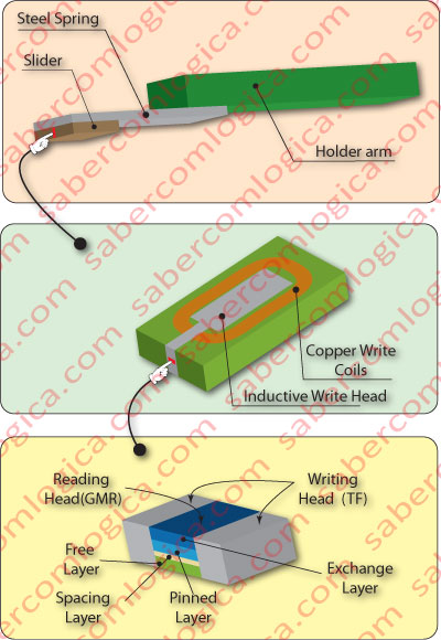
The GMR Heads (Giant MagnetoResistive), represented graphically in figure 2, are our next step on the evolution scale. Their sensitivity to current change is much greater than the MR heads, which guarantees its efficiency towards less strong magnetic fields. Its dimensions can also be greatly reduced. Of course, the term Giant has nothing to do with size, rather with magnetoresitivity.
The different layers that compose the MR head pass sequentially over the magnetic field:
- The free layer is the sensitive layer, and as the name indicates, it is free to spin according to the magnetic field it is exposed to.
- The spacing layer it’s non-magnetic but electric current conductor, like for example, copper. Its function is to separate the free layer from the pinned layer
- The Pinned Layer is made of cobalt material and is held in a fixed magnetic orientation by virtue of its adjacency to the exchange layer.
The Exchange layer is made of an “antiferromagnetic” material, typically constructed from iron and manganese, and fixes the pinned layer’s magnetic orientation.
Depending on the magnetic field to which the free layer is exposed to, the free layer will spin to its force, aligning or not to the pinned layer, to which the conductive or resistant state of the whole set corresponds.
That allows for the magnetoresitivity of the heads.
However, the recording process would still not allow to go over values between 100 and 200 Gb/in2. This was due to the superparamagnetic effect, which consists on having small particles (nanometric size) altering their magnetic orientation spontaneously under the effects of temperature, disturbing the information contained by them. It was necessary to find another method for magnetic recording.
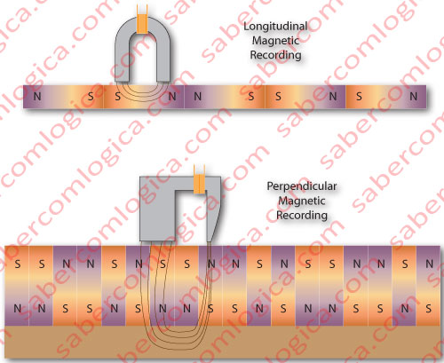
The PMR (Perpendicular Magnetic Recording) was the solution found to replace the longitudinal recording method, used at the time. Figure 3 tries to illustrate the differences between the two methods.
One will wonder: but won’t in this case the superparamagnetic effect produce consequences?
The Superparamagnetic effect varies in an inversely proportional way with the size of the particle and its coercivity, i. e., the smaller the particle and the smaller the coercivity of the material of the particle, the bigger the chance of the superparamagnetic effect occurring.
What is that coercivity thing?
Coercivity is the amount of energy to saturate a certain particle for a 0 magnetizing situation to occur. Let’s say that, the more coercive a material is, the stronger and resistant to magnetization it will be. On the other hand, the capacity to magnetize and to invert its magnetic orientation will have to be greater
This is where perpendicular magnetization plays a strong role. Since the incidence of the field produced by the head is punctual and vertical, it can be much more intense without affecting the adjacent fields, attaining, consequently, a much greater penetration capacity.
This allows, on one side, the magnetic film to be produced in a much more coercive material, and on the other side, to make it thicker, although reducing its longitudinal dimension. The thin mildly magnetic layer placed under this one plays a complementary role to the heads, in the production of the desired effect.
The magnetized particle, with its poles aligned vertically, allows the density to triple in the platters.
That’s how we were able to attain the current densities rounding the 400 Gb/in2 and the disks with 2 TB capacities, expecting a maximum density limit around 1 Tb/in2.
The TMR Heads (Tunnel MagnetoResistive), first appeared as adaptations of the GMR heads to the needs of perpendicular recording. The fundamental difference between GMR and TMR is in the replacing of the divider layer by a thin isolating layer between the free layer and the pinned layer.
If the isolation layer is thin enough (in the nanometer range), the electrons are able to flow from the free layer to the pinned layer in a perpendicular way. This way, it is possible to achieve simultaneously greater impedance and a much greater magnetoresisitivity.
The magnetoresistive effect results from the fact that electrons only flow if the magnetic fields of the free and pinned layers are aligned, as is the case for the GMR.
This type of TMR heads is currently the most used in HDD, mainly in cases of greater densities and perpendicular recording.
How they Move
We will now see how the heads travel between different points of the HDD, where the desired information is found.
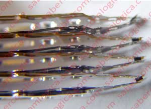
We’ve seen how the tiny and sophisticated reading/writing heads are fixated to the sliders in the graphics we presented earlier, and now we can see it in the Picture of figure 4.
The sliders that support the heads are attached to metal springs, which in turn are attached to supporting metal arms. These arms support one or two of these sets, depending if we are talking about the superior or the inferior arm, or the intermediate arms. The first two share only one side. The others use two sides of the platters (the inferior of one and the superior of another).
The (x) notes that we can see further on in this article refer to the figure 1. In order to follow this description you must click or touch it to open it in a new window.
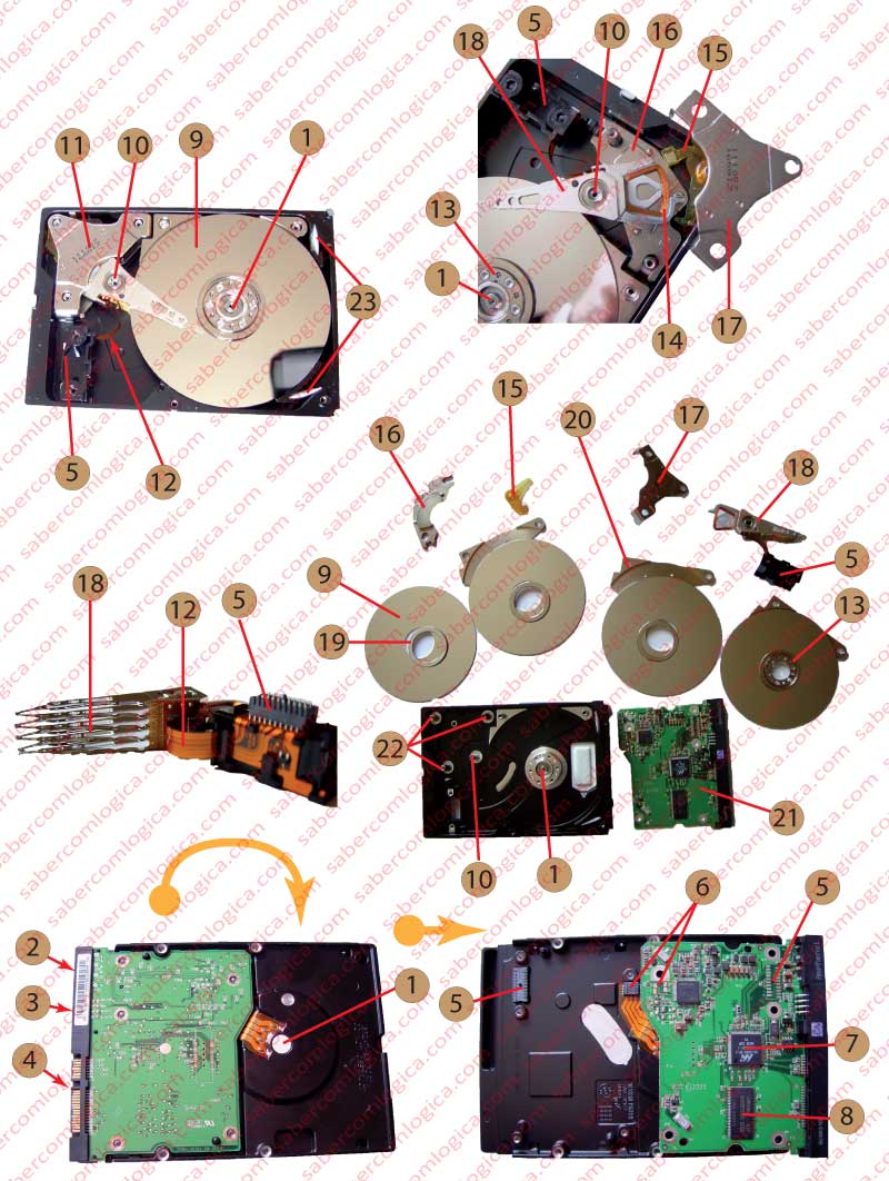
This set of support arms is connected throughout itself, moving as a whole around an axis (10). To this set we call Actuator (18) and its movement is regulated by the party that stands out beyond the set of arms, where the induction coil is placed (14). This coil is suspended between two potent magnets (16) which, according to the intensity and direction of the electric current in the coil, regulate the movement and position of the actuator.
The magnets are held by two pieces (17) that guarantee the distance between them in such a way that the coil can move freely amidst them. This part (15) serves as limitation for the movement of the actuator.
As we mentioned earlier, the heads hover at a nanometric distance from the platters without touching them.
And how do we manage that?
As we can see in figure 4, the heads outside the platters are pressed against each other (notice that some are already deteriorating – they can’t leave their natural means). Because of this, when the disc stops, the heads are immediately removed to a parking area, a small space in the platters reserved for that effect with no recording, where the heads finally touch the platters.
When the platters start spinning and reach cruising speed (let’s say 7200 RPM), a layer of air dislocates between the platters and the heads, causing an aerodynamic effect which drives them to oppose the force of the spring, keeping them from flying off. And everything is calculated so that they are lifted just enough, not too much, in which case they would not detect the small magnetic fields, and not too little, so they don’t touch the platter while it’s moving causing what is commonly called landing of the heads, and destroying the HDD.
We can’t phrase this enough, the aerodynamic movement in one way, the force from the springs in the other, they are calculated to make the heads hover over the platters rigorously at a few tens of nanometers, even in conditions with turbulence or small chocks.
We reinforce the fact that we are before a wonder of technology, where nano dimension is applied in an electromechanical device and it works.
Are the disks not hermetically sealed in a dust free environment?
Yes, they are. But not in a vacuum, like some people believe. How would it generate the aerodynamic effect if that were the case? There is air inside the HDD, renewable air, but it has to go through two entrances where we can find air filters (23).
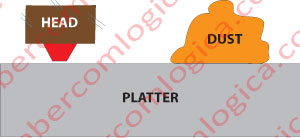
Just so you can better grasp the need to seal the disks in a dust free environment and filtering the air, we present a scheme comparing the distance of a head to a platter with a micro grain of dust in figure 5.
So, in short, the heads are held by metallic springs that are in turn supported by metallic arms. The arms that run between two platters hold two sets, and the upper and bottom arm hold one set each. The whole set, the Actuator, is in sync and moves as a whole, due to the existence of an inductive coil that is part of the Actuator and that moves between two magnets according to the intensity and direction of the electric current that goes through it. We stand before what is called a linear motor, which is used to the date.
Before, the actuator moved through a stepper motor, and each step corresponded to a track. Good times. This would not be possible with the current track density. But I’m going ahead of myself talking about tracks. We’ll get there. The linear motor, not only suffered from wear, as it didn’t adapt to the thermal expansion of the platters caused by temperature variation. And with information density, comes expiring dates.
The actuator communicates with the control plaque through a flexible ribbon that transmits data (12). It is connected to an element that establishes communication by contact with the logic board (5), after it’s inserted in the cavity meant for it. Note that the logic board is placed behind the box where the set of platters and the actuator are.