
Intel Nehalem (i7)
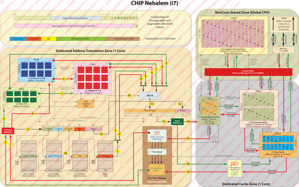
We’ve been analyzing the virtual memory regarding nonspecific 32 bits CPU. In order to understand in a better way the virtual memory we’ll do the analysis with graphical support of the address translation in the Intel Core i7 Nehalem, a last generation 64 bits quad core CPU. The Core i7 Nehalem has two TLB levels. The Level 1 is composed by two separated TLB, one for instructions and one for data, the first having 128 entries for instructions pages and the second having 64 entries for data pages, both 4 way set associated. These caches have a 4 clock cycles latency
The level 1 of TLB has two separated caches for great size pages (2 to 4 MB). The instruction one has 7 entries and is fully associative. The data one has 32 entries and is a 4 way set associative cache. In our analysis we’ll consider only 4 KB small pages.
The level 2 TLB is an integrated cache with 512 entries for data and instructions and is a 4 way set associative cache with a 7 clock cycles latency.
First we’ll analyze the composition of the pages tables’ entries. The i7 CPU with the Nehalem architecture are 64 bits CPU, thus its address space has 64 bits.
Although the address space has 64 bits, the Intel 64 architecture, the set of Assembly instructions defined to this CPU, only uses the lowest order 48 bits to represent the virtual address.
Having 48 bits to use to the addresses and knowing that the lower order 12 bits are designated to the offset as the pages have 4KB (212), we’ll have 36 bits to define the page.
This way we’ll have a pages table with 236 ≈ 68 billion entries. So being, it’s easy to understand the use of multilevel pages tables, precisely 4 levels, as we can see in Figure 1 note 18, corresponding each level to 9 bits of the virtual address.
Thus, each table will have 512 (29) entries of 64 bits, corresponding to a size of 4KB. Now we are dealing with a reasonable value, which allows us to keep in memory the level 1 page tables directory (permanently in memory) as well as the other pages tables directories levels and pages tables already queried.
Page Table Entry
If the validity bit is 1, i.e. if the entry refers a page in memory, the page table entry has the following meaning:
The 12 lowest order bits refer to some control signals necessary to security, state and other properties of the page referenced in the address, having each one the following mean:
- R designates if it’s read or read and write.
- U designates if it’s accessible in user or kernel mode.
- E designates the writing mode as write through or write back,
- CE designates if the content is or is not cacheable.
- P designates if it is a small or great page (only used for level 1 directory),
- C designates if this page is or is not removable from TLB in a process context switch situation.
- M is the dirty bit, designates if the page has been modified.
- A is the access bit, used by the OS to choose the pages to remove as we’ve already seen.
- V is the validity bit, designating if the page is in the memory or in the HDD (swap or pagefile).
R, U, E,CE, P and C are control bits which we are not going to analyze. They can have different meanings regarding the level of the table where they are: If they are in Pages Tables Directories entries they refer the properties of the child pages; if they are in a pages table entry they refer the physical page properties.
M, A and V are the bits we’ve already refer to or will refer in the future.
The 40 bits from 12 to 51 refer the physical page base address (concatenated with 12 zero lowest order bits), in the Pages Table entries or the address of the upper level pages if it´s an entry in a pages Tables Directory.
The remaining bits until 63, as well as the 3 bits before the address, are free.
The free bits are used in most elaborated implementations of the LRU replacement algorithm, for instance.
If the validity bit is 0, i.e. if the entry refers a page in swapfile or pagefile, then the bits from 1 to 63 will include a value used by the OS to locate that page in the HDD.
TLB Entry
One TLB entry must contain the virtual page base address and the physical page base address. The referred base addresses are composed by the 36 bits (virtual page) or 40 bits (physical page) of highest order of the address which must be concatenated with 12 lowest order zero bits in order to get the real base address. The virtual page base address is the one which is compared and the physical page base address is the one which is obtained in a hit case.
The TLB entry must contain the PID (process ID) in order to include simultaneously different processes translations.
The hyper-threading, when possible, as it creates 2 virtual processes from 1 process implies the existence of this identifier, the Virtual PID once both this new processes are going to share the resources of the one who gave birth to them and it’s necessary to identify to which of them refers the translation.
All the referred control bits must be contained in the TLB entry, since in cache hit case the respective Pages Table entry is not read and that information is needed.
Fetch Process
Now we’ll try to follow the path of an instruction in the Core i7, analyzing only one core.
The CPU core Control Unit sends an address of an instruction to be read, through the line described in Figure 1 note 1. This request is branched for parallel treatment by TLB and by the Pages Tables translation, as we can see in the lines of Figure 1 note 3 going through the Pages Tables and Figure 1 note 4 going to the TLB.
As both levels of TLB have latencies (4 clocks for L1 and 7 clocks for L2) when the process is dealt simultaneously if a TLB miss occurs it hasn’t to be restarted.
Following the TLB path, if a L1 TLB miss happens the instruction proceeds to L2 TLB (Figure 1 note 6). The L1 TLB results(Figure 1 note 4) as the L2 TLB (Figure 1 note 6), connect directly to a MUX whose task is select one signal between two, one coming from the TLB and another coming from the Pages Tables translation.
In order to get this, the TLB control unit sends a signal (Figure 1 note 10), if its told to do so by the TLB which got a hit, so allowing the selection of the entry coming from the TLB. When a TLB miss happens that signal (one bit) is not activated and the entry coming from the Pages translation will be selected (Figure 1 note 8).
The MUX selection (Figure 1 note 11) matches the physical page number which is then concatenated with the offset (Figure 1 note 12) in order to get the real address (Figure 1 note 13).
It’s this final address which is sent to the instructions cache of that core (Figure 1 note 14), beginning the process already described in the Chapter about Cache Memory which will return to the Control Unit the value of the requested instruction (Figure 1 note 15).
When decoded this instruction and if it contains a memory address (for data), as it is a virtual address a new identical process will start, but now for data.
That process is signaled with the green lines and with Figure 1 notes 1, 5 and 7, as the result comes from TLB L1 or TLB L2 and with Figure 1 note 9 when the result comes from the pages table.
The same process, as described for the instruction address, begins and the value of the data real address is sent to the data cache L1 entry buffers (Figure 1 note 16), the content of that memory position being returned to the CPU Execution Unit (Figure 1 note 17).
The description of these pathways, indicating the latencies for each of them, allows us to check the seek times for an instruction and to read or write a data in a given address.
We can see both the most optimistic and pessimistic situations:
- a cache hit in data and instructions TLB L1 and L1 Caches
- a cache miss in data and instructions TLB L1 and L1 caches and in TLB L2 and L2 and L3 caches, being necessary to get new pages from the disk and read from the memory the requested values. Both for instruction and for data.
Even given that in high percentage we’ll have a cache hit for both instruction and data TLB 1 and L1 cache, we are referring latencies in the order of 15-20 clocks. And we are being truly optimistic because we are considering various cache hits accumulated.
This way becomes obvious the importance of exploring the execution of the instructions in pipeline, out of order, hyper-threading or any other ways that allow us to have the maximum number of instructions executing simultaneously in the same core, but becomes obvious as well the importance of having several instructions of the same program executing simultaneously in each core of a multicore CPU.
Therein lays one of the current investments in CPU performance. Not in its clock frequency but in the instructions parallel execution, not only internally to each core through pipelining (as we saw in the Chapter on the CPU) but also through the execution of several instructions of a same program (tasks) in different cores of the same multinuclear CPU.
It’s here that programmers have a very important role. So, the better they know how the CPU works and how to use the tools that are available for concurrent programming, the most efficient their programs can be.