
Virtual Memory
But, if several programs can be executing simultaneously how does the developer to assign memory address spaces to the data and instructions of their programs not coincident with each other?
Yes that’s a problem. The developers run the risk of assigning coincident address spaces in memory to different programs. This way, when the program removed from the CPU is back to execution, everything is a mess in its address space.
Having this in mind the developers shall organize frequent covenants between them to agree together the memory address spaces each one will use. Preferably in good hotels and popular tourist regions, to offset the boring that will be the participation into a discussion only possible in the imaginary context, facing an indescribable confusion from which any solution will never arise.
As a solution to this issue, the OS has taken the place of these covenants and created for that purpose something called Virtual Memory, which has an address space with the size of the CPU registers:
- For 32 bits CPU and 32 bits OS the virtual address space is limited to 32 bits what corresponds to 4 GB.
- For 64 bits CPU and 64 bits OS the virtual address space is limited to 64 bits what corresponds to 16 Exabytes, although several OS impose lower limits.
Within these address spaces, the developers can choose any one, not even having to be careful to choose non coincident address spaces. They can even choose all them the same address space.
But that way we will have the same problem!
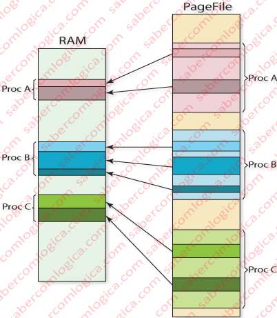
It’s here that the Operating System assumes its job and, supported by dedicated hardware structures, assigns different real memory address spaces to each created process. They are named as Process Address Space, each process having a different one (Figura 1).
But if the Process Address Spaces are not the same generated by the compiler for the program, how is it possible each program instruction to address the correct space?
For each address requested by the CPU the OS executes a translation process converting the virtual address (the one requested) into the physical address corresponding to it. It does it through tables reflecting the correspondence between virtual and physical addresses.
There’s no doubt that if that table would have the correspondence between each address its size and space used in memory would be monstrous.
For a 32 bits CPU the table would have 4,294,967,296 lines and 32 bits per line, having the small size of 17 GB. Obviously such table couldn’t be in memory thus the performance coming to unacceptable low levels. The problem had to be solved other way.
In order to do it the addresses were put together in blocks of contiguous addresses. These blocks can have several names, such as pages or segments and the memory division into them, paging, segmentation or paged segmentation.
In this work we’ll approach only the Pages, or Memory Pagination.
The referred memory blocks of contiguous addresses or Pages can have any size. For it to be defined it was necessary to consider that:
- Smaller Pages give a best control over the addresses loaded into memory but give rise to a table with a larger size.
- Larger Pages give a worst control over the addresses loaded into memory but give rise to smaller tables.
The Page size value is part of the machine architecture and cannot be changed. Currently the most commonly adopted value is 4 KB.
The correspondence of this value with the most usual Cluster value for an HDD is certainly not innocent. As we have seen, the lowest value that can be moved between the memory and the HDD is a cluster, which in the current case is 8 Sectors or 4 KB.
So let’s assume that the Page size is 4KB. We’ll need 12 bits to represent the contents of each page (212 = 4.096).
The addresses correspondence is then made up by Pages. Therefore, a 32 bit virtual address, has a 20 bits first part representing the pages and a 12 bits second part representing the offset within the referred page, and the offset within the address corresponds to the offset of the physical address (0 to 0, 1 to 1, 2 to 2, … and 4,095 to 4,095).
In order to implement this solution a new concept arose, the one of Pages Table (PT), where each one of the 220 different PTE (Pages Table Entries) indexes the Physical Page containing the address we want to map.
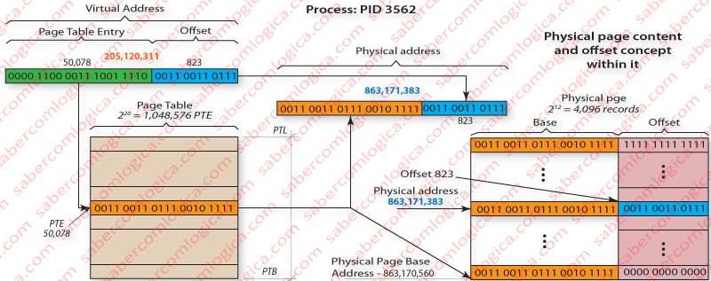
Let’s use Figure 2 to follow the description of how we map the virtual address 0000 1100 0011 1001 1110 0011 0011 0111 or 205,120,311 in decimal to the physical address 0011 0011 0111 0010 1111 0011 0011 0111 or 863,171,383 in decimal.
The virtual address first 20 bits 0000 1100 0011 1001 1110 or 50,078, designate the pages table entry where the base address of the physical page containing the record we want to map is registered. In that PTE nr 50,078 is registered the value 0011 0011 0111 0010 1111 which once added (concatenated) to the base address offset of the physical page, i.e. 0000 0000 0000, will compose the base address of that physical page 0011 0011 0111 0010 1111 0000 0000 0000 or 863,170,560 in decimal.
If we add the page offset at the virtual address, i.e. the value in its 12 last bits, 0011 0011 0111 we’ll get the intended address in that physical page
0011 0011 0111 0010 1111 0011 0011 0111
or 863,171,383 in decimal.
The Page Table will have 220 = 1,048,576 lines (entries), each one with 20 bits corresponding to the information it contains about the Physical Page location. For this to be possible the Physical Pages are always placed in memory so that its Base last 12 bits are all 0. This way, any real position within the Physical Page will be defined through the concatenation of the PT 20 bits with the Offset 12 bits, in our case 0011 0011 0111.
Thus the size of the Pages Table will be 220 x 20 / 8= 2,621,440 Bytes or about 2,6 MB.
Slightly different from the first situation, isn’t it?
This way it’s already possible to have the Pages Table in memory, what we’ve seen is mandatory for questions of performance, using a less significant amount of space.
Let’s go a little forward with the Virtual Memory concept, which is not confined to virtual addresses.
When a program is running, thus becoming a process, all the elements regarding it and necessary to its execution must be kept in the Main Memory. The problem is that the physical RAM isn’t in all cases enough to contain the full information regarding all the executing processes. We can even say that normally it isn’t.
Due to this fact, a program execution begins by mapping its instructions and data in the HDD in virtual blocks which will be part of a file named as Swapfile or Pagefile, containing or referring the objects within the HDD which are part of the executed mapping. As the name suggests it’s a file of pages to be swapped, where the pages composing each process are placed during its creation. To this procedure we call Pagination, reason why further on we’ll designate the referred file as Pagefile.
Obviously the OS has no way to determine which pages will be immediately necessary to the process. So being, the Pages Table is filled with indexes referring the entries in a Swap Table which in turn indexes the pages exact location in the HDD. The fact that those pages are not in memory is indicated through a control bit (V) existing in each Pages Table entry, whose function is precisely to inform the OS if that page is in Memory or in Disk, i.e. if it is Physical or Virtual.
The code, as it is in the executable file organized in the way it will be called, is normally paginated within the executable file itself. The OS opens that file, paginates it (divides it in blocks) and fills the pages table with an index for the swap table and with the value V=0. The Swap Table will index the code blocks in the exact place where the file lies.
Each time the CPU asks for and address in a page which is not in memory, that page is read from the Pagefile and written into memory. To this method we call Demanding Paging.
Alternatively, for each time a page is missing in memory (page fault) the OS can write in memory a series of pages which are in the proximity of the requested one. According to the locality principle, when an address in memory is requested most probably the next requested addresses will be in the proximity of the first one. To this method we call Anticipatory Paging.
Since we’ve talked about control bits we are going to refer to them. First we’ll talk about 3 of them which we’ll use in this work and after that we’ll refer the remaining. These bits can be found in each Pages Table Entry (PTE).
- V – Valid bit – When V=1 the address is valid for a translation into a Physical page. If V=0 the page is in the Pagefile.
- A – Page Accessed – This bit is set if the page is accessed. It’s used by the OS in the substitution pages policy we’ll see further on. If A=1 the page was accessed, if A=0 it wasn’t.
- D – Page Dirty – This bit tells the OS if the page was written, therefore if any of its elements was modified. If D=1 the content in some address belonging to the page has been modified, if D=0 it hasn’t.
There are several other control bits at each PTE referring to other of their characteristics, like:
- R defining if it’s read only or write/read.
- U defining if it is accessible in the User mode or in the Kernel mode.
- E defining the write mode as write through or write back.
- CE defining if its content is or not cacheable.
- P defining if it’s a large or a small page (only used at the level 1 directory – We’ll just see what this is).
- C defining if the page is or is not removable from cache (TLB) in each situation where switching processes gives rise to the cancellation of all TLB entries.
As we can see these last bits refer to concepts that we’ve not yet analyzed and we’ll see further on. We are not going to analyze them within this work. They have different meanings as the level of the page where they are:
- If they are at Directories Table Entries (DTE) they refer to the properties of the child pages.
- If they are at PTE they refer to the Physical Pages properties.
There still remain some free bits (for a 32 bits entry for instance) which will be used by the OS for most perfect implementations of the LRU algorithm for page switching, for instance.
Let’s move on.
When the CPU requests for an address which is not in any Physical Page, thus the V bit is 0, it happens a page fault and is launched an HDD reading process in order to find the indexed Virtual Page, read it and place it in memory, updating the Pages Table.
As we’ve seen, one or more processes can have coincident virtual addresses, which are translated into different physical addresses which are part of each process address space. When this happens with simultaneous executing processes, this means that we can have several different physical addresses (one for each process) for the same PTE (Page Tables Entry), what obviously is not possible.
That’s why each process will, have its own PT (Pages Table). Thus, the Pages Table is part of each process executing context, so being located at its address space.
How can we find the Pages Table in that space, i.e. how does the OS address it based in a virtual address?
For that purpose there are two CPU registers whose function is to keep two values contributing to it:
- Its lowest limit address or Pages Table Base (PTB) and
- Its size or Pages Table Limit (PTL).
Every time a process is withdrawn from the CPU this registers are part of the process context and are kept together with the remaining in the Kernel stack for this process created with this purpose, as we’ve seen before.
When the CPU reads a virtual address, it adds the first 20 bits value to the PTB and will have as a result the intended PTE.
This is easy to understand if we understand that the highest order 20 bits in a virtual address are the offset of the PTE within itself. If it’s 0 it will match to the PTB or the PT 1st entry. I it’s 1 it will match to the 2nd PT entry. If it’s 1,048,576 it will match the last PT entry.
So, we’ll have as many Page Tables in memory as created processes. The Page Tables will have more than 20 bits per entry due to the control bits. Let’s assume each PTE will have 32 bits in a 32 bits CPU.
So being, the Pages Table size increases to about 4,2 MB. If we’ll have 50 processes created then the memory space taken by the Pages Tables will be of 210 MB, which is significantly large and enough to allocate many Pages of a running process, thus increasing its performance. We must not forget that for a 32 bits CPU the addressable memory space is of 4 GB and that the OS reserves for itself values between 1 and 2 GB from that space.
To reduce the space used by the Pages Tables a new concept arose, the one of Multilevel Pages Table, where several levels of Pages Tables exist, each level addressing the intended next level Pages Table (in Disk or in Memory according to V) and only the last level addresses the intended Physical Page.
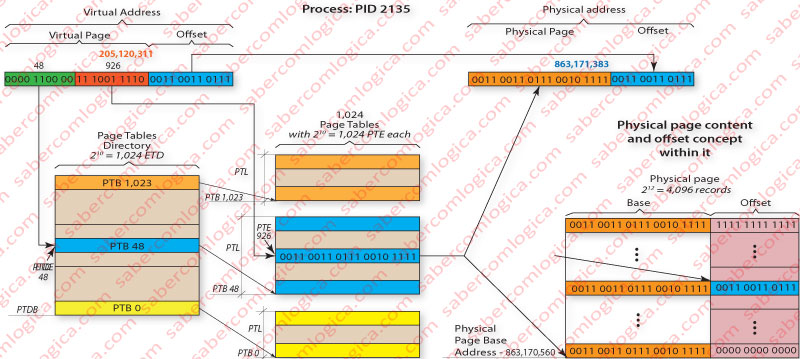
In order to better understand how this method of Multilevel Pages Table works we must follow Figure 3 in the mapping of the virtual address 0000 1100 0011 1001 1110 0011 0011 0111 or 205,120,311 in decimal to the physical address 0011 0011 0111 0010 1111 0011 0011 0111 or 863,171,383 in decimal, using a Two Level Pages Table. In this situation the highest level 20 bits of the virtual address are divided in 2 sets of 10 bits each.
The highest order 10 bits set refers a Table containing exclusively Pages Tables, reason why we’ll call that table as Pages Tables Directory (PTD) of Level 1 (the only Directory level in our case). The value of those highest order 10 bits, 0000 1100 00 or 48 in decimal, refers the Pages Tables Directory Entry (PTDE) whose content is the address of the Pages Table Base (PTB) we’re interested in, which must be loaded into memory if it isn’t yet.
The following order 10 bits set refer to Tables containing addresses to Physical Pages (in memory or in disk, according to V) thus being Pages Tables (PT). The value of theses 10 bits set, 11 1001 1110 or 926 in decimal, refer the Pages Table Entry (PTE) of the Table selected between the 1,024 Pages Tables through the value contained in the PTDE pointed by the first 10 bits set. That PTE contains the base address base of the Physical Page (in memory or in disk, according to V), we’re interested in.
To the Physical Page base address found, 0011 0011 0111 0010 1111 we concatenate the offset given by the virtual address lowest order 12 bits, 0011 0011 0111 and we get the intended Physical Address
0011 0011 0111 0010 1111 0011 0011 0111
or 863,171,383 in decimal.
Using this method it’s the Pages Tables Directory (PTD) of 1st level (the only one) which has to be always in memory. Only the Pages Tables (PT) referred by the PTD after each query will be called into memory.
The PTD size, assuming it will have 32 bits per line, will be 210 x 32 /8 = 4,096 Bytes or 4 KB. If we add to this value the referred PT, with 4 KB size too, we’ll use a total of 8 KB per process for addresses translation, significantly lower than the previous 4.2 MB. If there are 50 processes created the space used by the addresses translation will be of 400 KB, against the previous 210 MB.
Obviously, this method affects the system performance as it implies frequent accesses to disk. The ideal solution would lie in the existence of a Pages cache as we have for data and instructions.
Yeah, but indeed we have one for that matter. Its name is TLB (Translation Lookaside Buffer) and its task is to keep the PTE referring Physical Pages recently queried.
TLB (Translation Lookaside Buffer)
TLB it’s a cache with few entries, around some tenths. Since the Pentium generation is divided into Data TLB (for data pages) and Instructions TLB (for instructions pages). With this division was intended to preserve the capability granted by the Level 1 Caches of allowing the simultaneous access to data and instructions. The reduced number of entries is due to the fact that each TLB entry represents a Physical Page, thus 4 KB of addresses.
Always a virtual address is translated the TLB is queried before any other procedure. If a TLB miss happens the previously described method for the address translation is used and at the end an entry is registered in the TLB. What is intended using the TLB is the ability of having in cache a register of the last accessed pages. So being the policy of cache writing or substitution (whenever it is full) is the FIFO (First In First Out).
One TLB entry can or cannot include the identification of the process (PID – Process ID) associated to the registered translation. Including or not the PID leads us to different policies in the way we deal with the TLB registers:
- If the TLB entry doesn’t include the PID, each time the CPU execution context is changed (when the process being executed is changed) all the entries registered in the TLB are deleted. For this situation the most logic substitution policy is the FIFO. This situation is rarely used nowadays as the TLB cache size has significantly increased and its importance in the performance is recognized and submitted to more intense studies.
- If the TLB entry includes the PID, the TLB entries are not deleted each time the CPU execution context is changed, being possible to have simultaneously in the TLB entries from different processes. For this situation the most logic substitution method is no longer the FIFO as we can have most ancient pages which are the most used, referring for instance to a process which uses always the same pages every time it is in execution. The most logical substitution policy for this situation will probably be the LRU (Least Recently Used), which we have already referred when we dealt with the policies of block substitution in Cache Memory.
A new question arises. In a previous Chapter we have referred the Cache Memory, interposed between the CPU and the Main Memory. And now? What do we do first? Access the Cache Memory or the TLB?
We can face the two possibilities:
- The Cache Memory is accessed in first place and only if there’s a cache miss we go to the address translation in order to query the Main Memory. The Cache Memory will have virtual addresses
- The translation is executed first and only after that the Cache Memory is queried. The Cache Memory will have physical addresses.
The first solution is clearly the best one in terms of performance, but it allows the possibility of coexisting in Cache identical virtual addresses (from different processes) corresponding to different physical addresses, what invalidates (or turns very difficult) this solution. The second solution, although with worst performance, is the less complex and less error generator, reasons why it is the adopted in the last CPU generation.
The CPU manufacturers and their investigators give nowadays a very special attention to the TLB, given its great influence over the CPU performance. There are already several multicore CPU which use multilevel TLB. There are nowadays several investigations which point to multilevel TLB where the higher level, inclusive, is shared by all the CPU cores, as for instance the SLL TLB (Shared Last Level TLB in Chip Multiprocessors) or the Synergistic TLB for High Performance Address Translation in Chip Multiprocessors.
These proposals are based on the fact that in CPU multicore and multitasking, the various tasks of the same process running simultaneously are running into several separate cores and all go find TLB miss due to the inconsistency of caches. According to the proposed solution, TLB shared higher level, would ensure this consistency, and then the TLB miss would register only for the first task to view this page.
Page Replacement Policy
As we have seen, the code and data are paged and placed in a swap file, the Pagefile. Hence, they are transported into memory as required by the procedure, or by anticipation, if the execution algorithm so provides. But the memory space is very limited and the number of running processes can be very large. So being, the number of pages to put into memory per process is very limited.
Therefore, sometimes for a new page to be inserted into memory it’s necessary to remove another that is already there. When and how, is what we’ll see.
The OS keeps a table of the free pages and another one of the free modified pages. When we need to replace any page the OS uses one of these to make the switch, as they are already exempted from service.
And when? Let’s see an example.
The houses of a village are supplied by water deposits. All they have a deposit because, as water is a scarce and valuable resource, they will have to switch the supply between them. In order to get this purpose they set a minimum safety limit for the amount of water in the tank which defined when the deposit had to be refilled. They called it the low water mark.
They also set a maximum limit to fill the deposit which once reached the supply is closed, so that others can use the water for their deposits. They called it the high water mark.
That way, the water, such scarce resource, was enough for all the deposits.
Yeah. Our friend OS also has to manage a scarce resource, which is the time spent in conversation with the disc and the time spent checking which pages can be released from service in memory.
For this reason it created a deposit of free pages and two levels for it: The Low Water Mark and the High Water Mark.
We have thus defined when the replacement must be done. When the deposit reaches the low water mark, the OS will pay a visit to the inhabitants of the page table and choose between them whose must leave the house to make room for new ones. And it will choose as many as needed for the deposit to reach the high water mark.
This way the pages switch village deposit is refilled. Let us now understand how the OS chooses who should leave the house. It has several processes to do it.
The easiest one is the FIFO (First In First Out). It is apparently correct, as anyone who has longer enjoyed the house should give rise to new, but it can be bad for the house management, because sometimes the older ones in the house are the most needed there as they are more times called to service. They have frequently to be picked up again right after we send them away, so giving rise to two tasks to keep everything the same way.
The most efficient, as it takes care of the good house management in first place, id the LRU (Least Recently Used). By this method the OS always chooses the ones that were least recently called to service, therefore less useful to the house service. And how does he know who are those? By their age. Each inhabitant has a bit that, each time it is used is set to zero, thus becoming young again. It’s the Access Bit (A). And it has age bits too.
Periodically, the OS inspects the house and sets all the 0 bits to 1 and increments the age bits of those who are already 1. Once one habitant is called to service, its access bit is set back to 0 and he becomes young again.
When the OS has to choose who leaves the house it reads the age bits of those who are set to 1 and chooses the older ones which match the leas recently used.
The NRU (Not Recently Used) is a simplified version of the LRU where only the access bit A is used. When the OS has to choose who leaves the house it takes those who have A set to 1 and chooses randomly.
There are more ways for the OS to choose who leaves the house but these are already enough to make the difference between the easiest way (OS is less charged and replacements are most frequent)and the most efficient one (OS is most charged and replacements are less frequent).