
The Link Layer
Link is the route that a packet will travel from one host to another host. Let’s call those hosts as nodes in the network. Thus, link is the route between two nodes in a network, interfaces included in each node.
Interfaces are what we know as network cards, until some time ago as supplements in embedded PCI slots on the motherboard, now incorporated into the motherboard itself. We are referring to the most popular interfaces, namely Ethernet and Wi-Fi, that we’ll cover in this text.
So far, we have been talking about layers that provide delivery services end to end, i.e. between the browser and Web server shown in the Figure which in the previous articles as been with us during routing description. But, as we have seen in this figure, the packet moves node by node or link by link, in a HOP-by-HOP routing from source to destination. And on each link it can find physical means with completely different features and capabilities. It is precisely the Link Layer that deals with this. It’s its responsibility to move the frame through the link to NEXT-HOP router using the appropriate protocol to the characteristics of them physical mean of that link, always preserving the contents of the frame, ensuring reliable delivery.
Different protocols may or may not provide reliable delivery, using for that purpose methods for detection and correction of errors, only detection or none, using service request of packet retry of layer link, as is the case of radio transmission protocols such as Wi-Fi, or using flow control that add to the existing at TCP. In the link layer all nodes have a link address as they have an IP address in network layer. The address of the link layer is called MAC address.
MAC Address
MAC is the acronym for Media Access Control. MAC address is a unique address at global level, belonging to a network adapter or interface of a node. Any manufacturer of network adapters, even of those embedded in the motherboard, must purchase, at an international regulatory organization, a package of 24 bit addresses to all the parts it manufactures. The MAC address is composed of 48 bits. When a particular manufacturer is assigned with a package of lower order 24 bits, to the high-order 24 bits is assigned a value by the regulator that identifies the manufacturer. The MAC address is usually described in hexadecimal, with each byte separated by a dash (hyphen), e.g. E0-CB-4E-07-5E-03 is the type of a MAC address of an adapter.
Why more than one address?
For several reasons, including a very important one. While IP may vary depending on the value attributed to it by DHCP or depending on its location (in case of a laptop, a Tablet, a cell phone with Internet access), the MAC address is permanent and identifies a specific machine wherever it is.
MAC address is the one used on frames at the link layer, i.e. the frame header contains source and destination MAC Addresses.
How can a node know the MAC address of the node to which it is going to send the frame? It only knows its IP.
For this purpose we have ARP Protocol used by link layer to solve this problem.
ARP
The ARP, acronym for Address Resolution Protocol, is responsible for converting any IP address into a MAC address. But this translation is limited to the subnet where the node is inserted, i.e. the address resolution provided by ARP is limited to the subnet where such resolution is sought.
Because MAC address is the address used in the link layer, any node that wants to send a packet to another node on the same link must know the destination node MAC address. For this purpose each node should have an ARP table with the MAC addresses of all the nodes in its subnet. And actrually it’s almost like that
How does each node build its table?
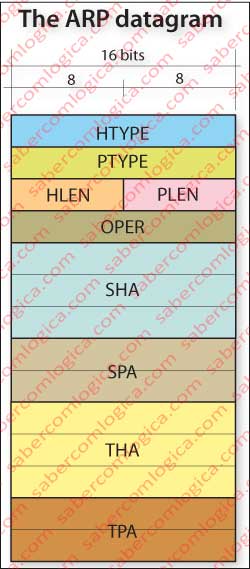
An ARP table is built on an “as needed” basis, i.e. when a node needs the MAC address of another node on its subnet it queries its ARP table. If that network address is not mapped to the corresponding MAC address, then the node performs an ARP query, building an ARP datagram and sending it to the subnet. Let’s see the rule of an ARP datagram, as shown in Figure 1, where:
- HTYPE – (Hardware Type – 16 bits), specifies the subnet hardware protocol type, e.g. Ethernet
- PTYPE – (Protocol Type – 16 bits), specifies the protocol for which the ARP request is directed, e.g. IPv4.
- HLEN – (Hardware Address Length – 8 bits), hardware address length in bytes, for example Ethernet is 6.
- PLEN – (Protocol Address Length – 8 bits), length in bytes of the address used in the layer above or in the specified protocol for which the request is made, e.g. IPv4 is 4.
- OPER – (Operation – 16 bits) specifies the operation that the node is performing. 1 for query and 2 for response.
- SHA – (Sender Hardware Address – 48 bits) represents the MAC address of the sending node.
- SPA – (Sender Protocol Address – 32 bits) represents the network address, for example, the IPv4 address.
- THA – (Target Hardware Address), represents the MAC address of the recipient left blank in the queries.
- TPA – (Target Protocol Address – 32 bits) represents the network address of the recipient, e.g. its IPv4 address.
Once built the datagram, ARP passes it to link layer to encapsulate it in the frame with the destination MAC address FF-FF-FF-FF-FF-FF, i.e. a broadcast to the subnet where the source node is located, at link layer level. Once the frame sent in link layer broadcast, all nodes in the subnet will receive the frame, open it and send it to an ARP module that checks if the network address contained in ARP datagram matches their network address. If it does, the respective node populates the ARP datagram according to the actual values of source and destination and puts its MAC address in the respective field, thereby mapping the network address to the MAC address. Then it sends the datagram to the link layer to the MAC address of the node that issued the query.
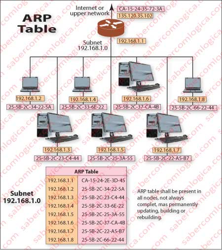
Thus, the node now querying can fill its table with this mapping and, based on updated table lookup, send the IP datagram that was queued. Figure 2 is an example of what can be the ARP table for a subnet as shown in this figure.
You have probably noticed that we referred to ARP datagram, although this protocol doesn’t belong to the network layer, as it contains MAC addresses. But it doesn’t belong to link layer too, because it has network addresses. Let’s say it’s halfway there. Thus we chose datagram name to distinguish it from the frame in which it is encapsulated at link layer.
Let’s now track a package on its journey through the data link layer, corresponding to a request from a client node of AS4 subnet d, which is represented schematically in Figure 4 of the previous article. It’s a request made by node 85.136.38.130, a desktop connected by wire to the network, thus using the Ethernet link layer.